I have that fuse of 100A but it's for the amp not near the battery😕, because i already use a fuse near the battery of the car😕
i just need a fuse for the amp. is it that you say? sorry it's my bad english and i have difficulties to understand what you say 😱
can you confirm me that please?
Thanks 🙂
i just need a fuse for the amp. is it that you say? sorry it's my bad english and i have difficulties to understand what you say 😱
can you confirm me that please?
Thanks 🙂
you don't need to fuses, you need one and that one is the on that goes from battery +
That is right, battery > fuse > amp
That is right, battery > fuse > amp
Ok thanks 🙂
but for me we need fuse placed near the battery at max 30cm "to protect the car if the wire is cut and make fire in the car due to a short circuit for exemple" and a fuse for the amp to protect speaker if the amp fail.
I don't know but on the manual of my soundstream they are fuse near the battery and fuse in the amplifier 😕
and my sinuslive don't have integrated fuse, the fuse is external for him 😕
what do you think if your amp will fail, what's going to happen to the fuse that is up front? you do not need 2 fuses, you need one fuse from battery to amp, and that one is close to battery, pointless to have 2
Fuse is fuse, you don't need 10 to do the same job and only 1 does
Scenario where you would need to is, say you have more then one amp on that battery, then you would have one fuse up front to protect cables, and then one fuse for each amp, up front would be the biggest rating fuse, then would be for sub amp, and then for any other amp
Hello
yes it is logical to think that 🙂 but why constructor ask for one fuse near the battery "less 30cm" 😕 and other fuses who are in the amp to protect the amp.
for me we need 2 fuses because if there is a problem in the amp, the fuse should be as close as possible to the amplifier
Perry have you got a suggestion please about that, because me and luka have different opinions on the subject 🙂
for the moment the amp doesn't work so it's for the futur
Thanks 🙂
Do you have any other amps drawing power from this wire?
What's the suggested fuse for the amp?
What's the suggested fuse for the amp?
For the sinuslive the suggested fuse is a 100A and i have a rockford fosgate punch 200.4 who use a 30 A fuse.
There's more than one safe way to power the amplifiers.
If the 100 amp fuse doesn't blow with both amps drawing current through it, you can use the single fuse but it leaves you with the problem of tapping off of the wire for the second amp. This assumes that the wire is capable of passing 100 amps of current safely.
In my opinion, since you have two amps, you should use a distribution block. If you have wire that's ~25mm^2, you can use a 150 amp fuse at the battery (if I did the conversion correctly). Then you'd use the proper fuses for each amp in the distribution block.
HTML:
In my opinion, since you have two amps, you should use a distribution block. If you have wire that's ~25mm^2, you can use a 150 amp fuse at the battery (if I did the conversion correctly). Then you'd use the proper fuses for each amp in the distribution block.Hello 🙂
I think you are right i just nead confirmation thanks Perry 🙂
Hello
i have question about 4 condensators who are in series on the pcb, they are placed in series with the negative poles?
Is it normal? what is the purpose of such an arrangement?
the condensators are 22µF 250V
I do a little schematic under microsoft paint
Thanks for teaching me
i have question about 4 condensators who are in series on the pcb, they are placed in series with the negative poles?
Is it normal? what is the purpose of such an arrangement?
the condensators are 22µF 250V
I do a little schematic under microsoft paint
An externally hosted image should be here but it was not working when we last tested it.
Thanks for teaching me
They are part of the output filter. They are polarized capacitors and have AC voltage applied. If each of the capacitors were directly connected across the output, it would have reverse voltage applied for one half cycle of the waveform and the capacitor would leak (electrically) and DC or very low frequency signals would pass through the capacitor (not a good thing). Connected as they are, this can't happen.
Using non-polarized capacitors is probably better but this works well enough in many amps and the capacitors are readily available.
Using Mylar capacitors is even better but they're more expensive and typically much larger for the same value and the voltage.
Using non-polarized capacitors is probably better but this works well enough in many amps and the capacitors are readily available.
Using Mylar capacitors is even better but they're more expensive and typically much larger for the same value and the voltage.
ah ok i understand now 🙂
Do you remember when i tell you that the core is warm? so it's more warm when i replace theses condensators whith new condensators who have the same value? i don't know why?
Do you think i can replace them with non polarized condensators?
if yes
is it obliged to put the same value capacitors?
I have bought this to mesure caps and test it, i find it very usefull 🙂
SELECTRONIC ::: L'univers électronique :::
When i power up the amp i can hear a little noise in continu like a sound of electricity in the speaker 😕
the pop noise is not present if i replace 4 condensators of 22µF 250V with new but i hear this strange sound and the core is very warm but the sound is great better than before
Can you explain me that please?
Thanks Perry 🙂
Last edited:
If you replace the capacitors in the output filter, you should replace them with the same value.
Is it possible that you pulled a via in the circuit board when replacing the capacitors? If that happened, the effective capacitance would be 1/2 of what it should be and that could cause problems in the output filter (the inductor is part of the output filter).
Is it possible that you pulled a via in the circuit board when replacing the capacitors? If that happened, the effective capacitance would be 1/2 of what it should be and that could cause problems in the output filter (the inductor is part of the output filter).
Euh sorry Perry but my english is limited and i'm not sure to understand what you say:😕
"Is it possible that you pulled a via in the circuit board when replacing the capacitors?"
I don't understand:
"you pulled a via in the circuit board "
Sorry 😱
"Is it possible that you pulled a via in the circuit board when replacing the capacitors?"
I don't understand:
"you pulled a via in the circuit board "
Sorry 😱
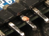
The vias are the copper cylindrical conductors that connect one side of the board to the other. If the solder isn't 100% removed around the component lead so that it requires significant force to remove the component, the vias are ripped out of the board. It's not always obvious that it has happened. The attached photo shows one example where part of a via was damaged (small piece of copper on the pin of the board).
Attachments
Hello Perry
Thanks
Ok i understand now 🙂
so no i haven't pulled a via when i've replaced condensators.
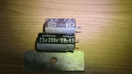
The fourth new condensators are: nichicon 22µF 350V serie VR(M)
The fourth old condensators are: FKE 22µF 250V
i attached a photo to show you new and old condensators.
do you think new condensateurs may warm up the coil? for me there is no reason but i'm not really sure now....
Thanks 🙂
Thanks
Ok i understand now 🙂
so no i haven't pulled a via when i've replaced condensators.
The fourth new condensators are: nichicon 22µF 350V serie VR(M)
The fourth old condensators are: FKE 22µF 250V
i attached a photo to show you new and old condensators.
do you think new condensateurs may warm up the coil? for me there is no reason but i'm not really sure now....
Thanks 🙂
Attachments
I know of no reason why those capacitors would cause the problem. When you measured the temperature of the output inductor before replacing the capacitors, are you sure the ambient temperature was the same and that you allowed precisely the same time from start-up to the time when you measured the temperature?
No the external temperature is more hot when i do my test 😱 🙄
so i just put my new condensators and do a valid test....
so i just put my new condensators and do a valid test....
the defective capacitors is one of the four capacitor of 22µ 250Vdc
with my capacimeter
SELECTRONIC ::: L'univers électronique :::
i test the four condensators and the result is:
22.8µf
21.3µf
25.7µf I think it's this condensator who is defective because i can see signs of leakage below the capacitor
22.8µf
The new capacitors have been mesured and all have 20.8µF
with my capacimeter
SELECTRONIC ::: L'univers électronique :::
i test the four condensators and the result is:
22.8µf
21.3µf
25.7µf I think it's this condensator who is defective because i can see signs of leakage below the capacitor
22.8µf
The new capacitors have been mesured and all have 20.8µF
- Status
- Not open for further replies.
- Home
- General Interest
- Car Audio
- SinusLive SL-A1500 help needed.