Lumanauw,
You ask me explain my religion!! Tricky, better put on your flame suit........😀
Fully complementary circuitry looks great on paper, I like it a lot.
However, any distortion it introduces is symmetrical, in a sense, 'balanced'. To many, this appeals. But symmetrical distortion on an audio waveform is the stamp of odd order harmonics; even order distortion is asymmetrical.
Thus, I like a single diff pair, as the voltage amplifier is driven in single end. This introduces even order distortion which is very well tolerated by humans, and while there is odd order certainly present, it is partially masked by the even order.
While the single diff pair doesn't look as nice as a fully complementary diff pair structure, it sounds better, to my ears.
I must stress this is my belief, and YMMV, and probably does. Everyone is free to pursue their own religion with passion and commitment; I'm pretty cool about this! 😉
Sampai pertanyaan saudara!
Cheers,
Hugh
>lumanauw
I want to inform you that this amplifier was published by Matti Otala in 1973.
He has introduced new term of TIM distortion and theory which explained the reason of "transistor sound" of semiconductor amplifiers - SR parameter and depth of feedback loop.
A commercial version of this amp was manufactured by Electrocompanient. Otala co-operated with Harman/Kardon in projecting Citation power amps, too.
AKSA, apa kabar istrinya, baik-baik?
My personal preference is also single differential. The sound it produces is just right, compared to complementary differential.
But for the VAS, I liked it push-pull VAS. (in this, I'm quite different with you).
Dual differential is another story. Like the Otala design, it gives more character to the sound it produces. Maybe it is because dual differential makes large open loop? Is that big feedback is not so bad?
Look at post #261. Q1 is giving distortion cancelation from left half to right half transistor. Q1 is also giving distortion cancelation with Q2. So there is "Double cancelation" works on full complementary differential.
Maybe what J Curl stressed is in Jfet differentials, because my experience is always with bipolar differential. For bipolar differential, I certainly likes single diff.
(too bad I cannot buy K389-J109 pairs here, other wise I would have experimented with full Jfet complementary differential, like J Curl uses)
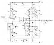
This design has single differential, and pushpull VAS. The levelshifter is done by folded cascode. (leading to low openloop gain) The output of right differential is converted to drive lower VAS transistor with current mirrors. This is from AD817 opamp.
Can anyone help, if I want to make this design an audio power amp, what is the bias current for Differential, Folded cascode, and final transistor? The supply is about +/-50V.
My personal preference is also single differential. The sound it produces is just right, compared to complementary differential.
But for the VAS, I liked it push-pull VAS. (in this, I'm quite different with you).
Dual differential is another story. Like the Otala design, it gives more character to the sound it produces. Maybe it is because dual differential makes large open loop? Is that big feedback is not so bad?
Look at post #261. Q1 is giving distortion cancelation from left half to right half transistor. Q1 is also giving distortion cancelation with Q2. So there is "Double cancelation" works on full complementary differential.
Maybe what J Curl stressed is in Jfet differentials, because my experience is always with bipolar differential. For bipolar differential, I certainly likes single diff.
(too bad I cannot buy K389-J109 pairs here, other wise I would have experimented with full Jfet complementary differential, like J Curl uses)
This design has single differential, and pushpull VAS. The levelshifter is done by folded cascode. (leading to low openloop gain) The output of right differential is converted to drive lower VAS transistor with current mirrors. This is from AD817 opamp.
Can anyone help, if I want to make this design an audio power amp, what is the bias current for Differential, Folded cascode, and final transistor? The supply is about +/-50V.
Attachments
I try to take part in this thread but I do not recognise what a kind of DIY society discuss here. I remember that pupil should keep his mouth shut when teacher is speaking. ;-)
Lumanauw,
Istri baik-baik, terima kasih, selalu tersenyum!
You asked me my thoughts on Sky-Chu's circuit; here goes!
I do not like the complexity, and particularly the large numbers of cascodes. I accept that with Jfets, cascodes are necessary because of the limited Vce ratings, but I have not found they add anything to the sonics, although they look great....... .
Current sources are difficult mistresses. Once again, they look great, but unless they are implemented very carefully, they can turn on you and destroy the sonics.
There are large numbers of devices in this circuit, some of them quite costly, and this goes against my religion. I have built such amplifiers, and generally found that complexity does not improve the sonics. The solution to good sonics is a simple circuit, very carefully chosen operating points, and great care with component selection. Anything else is all too often academic self-indulgence.
Further, this is a voltage amplifier only, and if we are talking of power amplifiers, which usually include a nfb loop, this schematic is only half the picture. Nfb introduces all sorts of issues which must be considered in totality. And all too often nfb is necessary!
Unfortunately I haven't the time right now to explain precisely why largely because I'm not actually too sure why these things are problematic. But I am convinced that simplicity is the key.
Try an AR Bailey amplifier from the sixties, using modern semiconductors. You will be surprised! Or perhaps Le Monstre, from Jean Hiraga.
Cheers,
Hugh
Here's lesson I capture from you
Is there any guideline for component selection? Is this more about the brand? Or it is completely trial and error?
I've got 1 question about differential. Why is that in non-feedback amp design, the differential is almost always using full complementary differential? Is it imposible to built non-feedback audio power amp using single differential?
CCS can be replaced by R+bootstrap. What is the meaning of Bootstrap? Putting C between 2 R's is bootstrap?Current sources are difficult mistresses. Once again, they look great, but unless they are implemented very carefully, they can turn on you and destroy the sonics.
and generally found that complexity does not improve the sonics
Operating points, that is very important. I've heard difference from only 1mA difference in bias.The solution to good sonics is a simple circuit, very carefully chosen operating points, and great care with component selection. Anything else is all too often academic self-indulgence.
Is there any guideline for component selection? Is this more about the brand? Or it is completely trial and error?
Passlab designs are simple, but they do perform better than more complex designs.But I am convinced that simplicity is the key.
I've got 1 question about differential. Why is that in non-feedback amp design, the differential is almost always using full complementary differential? Is it imposible to built non-feedback audio power amp using single differential?
This is silly question, but I want to know why. Is there any opamp or chipamp designer here?
Why is that every topology inside opamp and chipamps always using single diffential?
Why is that every topology inside opamp and chipamps always using single diffential?
first, i'm assuming you really mean parallel complementary differential input stages - there are in fact many series dual differential stage op amps, particularly high precision types with high open loop gain
maybe because their is no objective, salable datasheet spec that is improved by complementary differential inputs?
op amp designers are driven by cost/yield/process complexity vs measurable performance
early op amp designers didn't have reasonably complementary devices, only since the 90's have good complementary processes been broadly available
current feedback op amps usually have symmetric input stages and some modern low voltage rail-to-rail input op amps do use dual complementary input diff pairs
Walt Jung's "Op Amp Applications" book is a valuable reference work of op amp design history and shows examples of many of these devices
I'll take a stab:
hmmm ... let's see ... it's cheaper 🙂
mlloyd1
by the way, there were some harris high speed op amps some years ago that used complementary differential input stages. Wish i could remember some part nubers, but for some reason, I can't at the moment.
hmmm ... let's see ... it's cheaper 🙂
mlloyd1
by the way, there were some harris high speed op amps some years ago that used complementary differential input stages. Wish i could remember some part nubers, but for some reason, I can't at the moment.
lumanauw said:This is silly question, but I want to know why. Is there any opamp or chipamp designer here?
Why is that every topology inside opamp and chipamps always using single diffential?
Lumanuaw!The distortion isn't cancelled by Q1 and Q2.
I simulated Slone'topo .The sim say that the distortion still alive.
I built a Slone amp which use collector resistors instead of current mirror.
I didn't succeed in current mirror.I don't still know what reason is.
Advantage of Slone's topo is the cacellation of voltage offset.It can't cancel distortion.
thanh said:...I built a Slone amp which use collector resistors instead of current mirror.
I didn't succeed in current mirror.I don't still know what reason is.
If you are refering to Figure 7.6a of Slone book, you are not the only one with that problem. I have not built it but I have discussed that with mcp and because of use of current mirrors for loads in first stage there is an imbalance for the dc operating points (VAS: Q11 and Q12) of the amp resulting sometimes in the output swinging to either positive or negative rails. Q14 and Q17 impose a maximum collector current for the VAS stage but it is only there for protection not normal conditions.
Conventional current mirrors take no account of the bias current of the VAS. Consequently, they balance only the currents into the current mirrors; not the currents coming out of the diff pair.
Consequently, the diff pair is not in balance and residual distortion and overload margin are compromised. Listening tests tell me this is very significant sonically.
A resistor in the working arm of the diff pair, with the other arm taken to rail, is a better arrangement. But you must match the beta and the bias networks of the diff pair transistors (and carefully dimension the arm resistor) for this to work. I routinely get better than 2% balance with no special technique here, measured from the voltages across the (equal) bias resistors.
Cheers,
Hugh
AKSA,
Who are you responding to with your last comment? I believe that your comments are not related at all to my last post since there is no obvious relation.
Who are you responding to with your last comment? I believe that your comments are not related at all to my last post since there is no obvious relation.
How would this pair of seemingly complimentary J fets work in an All Complimentary style Differential Amp.
http://www.onsemi.com/pub/Collateral/2N5460-D.PDF
http://www.onsemi.com/pub/Collateral/2N5457-D.PDF
http://www.onsemi.com/pub/Collateral/2N5460-D.PDF
http://www.onsemi.com/pub/Collateral/2N5457-D.PDF
ppl said:How would this pair of seemingly complimentary J fets work in an All Complimentary style Differential Amp.
http://www.onsemi.com/pub/Collateral/2N5460-D.PDF
http://www.onsemi.com/pub/Collateral/2N5457-D.PDF
See my post http://www.diyaudio.com/forums/showthread.php?postid=360365#post360365.
This example is for an op-amp or pre-amp but could be used as a driver stage for a power amp if we add a bias stage.
I have built an adapted pre-amp design about 14 years ago using this symetrical complementary jfet diff input stage. See my post http://www.diyaudio.com/forums/showthread.php?postid=360361#post360361.
But today, I would recommend using matched jfet pair in same package instead of 2N5457/5460 for ease of DC offset adjust and jfet bias current setting. See also fig 2 of this Borbely link:
http://www.borbelyaudio.com/xover.pdf for another op-amp.
mlloyd1 said:(...)by the way, there were some harris high speed op amps some years ago that used complementary differential input stages. Wish i could remember some part nubers, but for some reason, I can't at the moment.
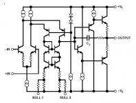
It was the HA-2539, and the HA-2540. See http://www.stanford.edu/class/ee214/Handouts/ho15opamp.pdf
Data sheet is at http://www.intersil.com/data/fn/fn2896.pdf. This op-amp has a complementary input stage with a folded cascode.
Hi Fab,
Yes, you are right, I was responding to Thanh's comment here:
Hugh
Yes, you are right, I was responding to Thanh's comment here:
I didn't succeed in current mirror.I don't still know what reason is.
Hugh
Some of opamps have incredible specs. Very high slewrate, very high bandwith etc.
1. Does anyone has built audio poweramp following the topology of these "superspec" opamps?
2. These opamps, in their datasheet, are not supposed for audio. What will be the sound like, if we use it for audio, like making preamp with it? Is the topology for audio opamp has certain topology, that differs from these opamps?
It was the HA-2539, and the HA-2540. See http://www.stanford.edu/class/ee214...s/ho15opamp.pdf
Andy, your correct I still have some samples left from the 80's and never used them. One of them even in a 14 pin package. At the time I was into using PMI OP16 and 17's and OP37.🙂
- Status
- Not open for further replies.
- Home
- Amplifiers
- Solid State
- Single or dual differential?