Miller Effect
The Miller effect is reduced by using a cascode pair or a current mirror on the diff amp. As for as CMRR goes if the hfe or Tranconductance is not matched in the diff pair the CMRR will get worse as the miss match increases.
In addition, I do not see the point in trying to compensate for the effect at the second stage. I have never seen it work, however you can build a filter there.
Cool, Curl get runner up to new product of the year in StereoPhile.
Most be a Dam fine sounding amp.😎🙂
AKSA said:Pavel,
I know the linearity of the drivers and output devices is very important to sonics, as is Vbe and beta matching of like devices where output pairs are used.
I did the side by side comparison with 2SC5200/2SA1943 on both; one, a CFP (with 100R base emitter resistor on the outputs) and the other a DEF Type II with 150R/100nF between driver emitters.
There really was no comparison, with DEF being superior, particularly in engagement, whatever the hell that means.......
Your work on low pass input filters is confirmed by Jonathan, in fact. That's good enough for me. No doubt; unless the amp is intrinsically band limited elsewhere, and probably despite that, we should use them liberally!
Do you chime them in at say 3dB down at 50KHz?
However, polystyrene or mica - that is the question!
Cheers,
Hugh
Hugh,
I was thinking about our different experience with CFP x DEF. There might be one difference - my circuit is a true class A for 8 Ohms (Iq even higher than shown) and was compared to class A DEF. How about you, did you test class AB or class A output stages? In case of class AB output stage I believe that DEF would give better sonic results (remember the thread about CFPs about a year ago, do not want to go into details now).
Regarding filtration - it is about 90 kHz/-3db as a result. But not only input RF filter, but every stage is in fact a LPF (with RC defined pole). I do not use global FB, but the amp is divided into say 3 stages with local FBs [this is done for preamp and power amp as well], every stage is a LPF. This brought results, and you can hear it comparing versions with and without LPFs in individual stages. I should mention that the amp's construction must be done the way that does not allow the RF signal to bypass filtration.
Cheers, Pavel
Pavel,
I've just read through John Curl's Parasound JC-1 amplifier. WOW!! (this reads 'walk on water'!). Very, very impressive. Such a luxury to have three men behind every product; design, layout and component choice. Should work well!
I used a Class AB bias to just less than 60mA.
I also agree that in Class AB, the DEF will perform better as short term oscillations would appear to be easier to control with base stoppers. In Class A, I would expect CFP to give better FR and damping factor, and possibly bias control too. It's a very attractive topology, plagued only by low current local instability. I first found this topology in an engineering text from the early sixties. The application note commented that Zout was around ten times less than a conventional emitter follower; I call it the monkey atop the elephant.
I should comment on multiple outputs of dubious linearity, like the BD243. Matching for Vbe and beta is important; it won't sound much good until the former is within 1mV and the latter within about 2%. This alone could explain a few of the observed differences.
I admit to looking carefully at the circuits on your site with admiration. Nicely done; some very deep thinking, and my thanks for this work. And yes, layout is crucial, particularly short feedback paths and shielding from RF input. I find your comments about RF filtration fascinating; it would seem best to place it outside the feedback loop at the input; this is an area I need to research more.
On Type 1 v. Type 3: To absorb tolerances and keep bias stable, it is indeed necessary to use considerable degeneration on the emitters of the VASs with Type 3 (fully complementary diff input stage). This pulls back open loop gain very considerably, where such artifice is not necessary with Type 1. In most cases, and even with resistor loading at the collector of the diff pair, the OLG of the Type 1 will be higher, leading to higher feedback factors. Whether this is an advantage is moot, of course. A factor in favour of Type 3 is the fact that two VAS devices are now driving the output stage, which improves drive power and better resists reactive reflections from the speaker back through the output stage.
Jewilson: I have found constant current sources on the diff pair a mixed blessing. Better CMRR, yes, but much thinner sound. There is clearly a sonically pleasing quality in resistor drive to this stage, but PSRR suffers......
On Miller compensation: I have found it should be used sparingly; back off until unstable, then add about 25% to confer unconditional stability. Even so most SS amps with GNFB will kick up with highly capacitive loads like ES speakers. But it is palpable that reduction of Cdom always seems to improve sonics
Cheers,
Hugh
I've just read through John Curl's Parasound JC-1 amplifier. WOW!! (this reads 'walk on water'!). Very, very impressive. Such a luxury to have three men behind every product; design, layout and component choice. Should work well!
I was thinking about our different experience with CFP x DEF. There might be one difference - my circuit is a true class A for 8 Ohms (Iq even higher than shown) and was compared to class A DEF. How about you, did you test class AB or class A output stages? In case of class AB output stage I believe that DEF would give better sonic results (remember the thread about CFPs about a year ago, do not want to go into details now).
I used a Class AB bias to just less than 60mA.
I also agree that in Class AB, the DEF will perform better as short term oscillations would appear to be easier to control with base stoppers. In Class A, I would expect CFP to give better FR and damping factor, and possibly bias control too. It's a very attractive topology, plagued only by low current local instability. I first found this topology in an engineering text from the early sixties. The application note commented that Zout was around ten times less than a conventional emitter follower; I call it the monkey atop the elephant.
I should comment on multiple outputs of dubious linearity, like the BD243. Matching for Vbe and beta is important; it won't sound much good until the former is within 1mV and the latter within about 2%. This alone could explain a few of the observed differences.
I admit to looking carefully at the circuits on your site with admiration. Nicely done; some very deep thinking, and my thanks for this work. And yes, layout is crucial, particularly short feedback paths and shielding from RF input. I find your comments about RF filtration fascinating; it would seem best to place it outside the feedback loop at the input; this is an area I need to research more.
On Type 1 v. Type 3: To absorb tolerances and keep bias stable, it is indeed necessary to use considerable degeneration on the emitters of the VASs with Type 3 (fully complementary diff input stage). This pulls back open loop gain very considerably, where such artifice is not necessary with Type 1. In most cases, and even with resistor loading at the collector of the diff pair, the OLG of the Type 1 will be higher, leading to higher feedback factors. Whether this is an advantage is moot, of course. A factor in favour of Type 3 is the fact that two VAS devices are now driving the output stage, which improves drive power and better resists reactive reflections from the speaker back through the output stage.
Jewilson: I have found constant current sources on the diff pair a mixed blessing. Better CMRR, yes, but much thinner sound. There is clearly a sonically pleasing quality in resistor drive to this stage, but PSRR suffers......
On Miller compensation: I have found it should be used sparingly; back off until unstable, then add about 25% to confer unconditional stability. Even so most SS amps with GNFB will kick up with highly capacitive loads like ES speakers. But it is palpable that reduction of Cdom always seems to improve sonics
Cheers,
Hugh
Sounds great and is more filtering
"I have found constant current sources on the diff paira mixed blessing. Better CMRR, yes, but much thinner sound. There isclearly a sonically pleasing quality in resistor drive to this stage,but PSRR suffers"
 Well...... that's fairly easy. The knob on the front of the amp can be called the "HD" dial or maybe even the "Dean Dial"

"I have found constant current sources on the diff paira mixed blessing. Better CMRR, yes, but much thinner sound. There isclearly a sonically pleasing quality in resistor drive to this stage,but PSRR suffers"
Well...... that's fairly easy. The knob on the front of the amp can be called the "HD" dial or maybe even the "Dean Dial" Attachments
What is TEF, DEF, CFP? Please insert drawing.
EF=Emitor Follower, CFP= Collector output? TEF=? DEF=?
EF=Emitor Follower, CFP= Collector output? TEF=? DEF=?
EF = emitter follower
CFP = complementary feedback pair
DEF = two stage (or dual) emitter follower
TEF = three stage (or triple) emitter follower
CFP = complementary feedback pair
DEF = two stage (or dual) emitter follower
TEF = three stage (or triple) emitter follower
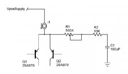
I call it the "faultless" front end
http://www.diyaudio.com/forums/showthread.php?s=&threadid=22260&perpage=15&pagenumber=16
http://www.diyaudio.com/forums/showthread.php?s=&threadid=22260&perpage=15&pagenumber=16
hitsware,
you might like to have a look at the front end from http://www.borbelyaudio.com/dc102.pdf, this I consider to be one of the best front ends ever published.
you might like to have a look at the front end from http://www.borbelyaudio.com/dc102.pdf, this I consider to be one of the best front ends ever published.
Thanks !
WAY to complex for my tastes .....
I'm sure it's good BUT ....
No accounting for taste ....
I like 3 xsistors for the whole amp ...
But in the case of a dif amp front end
will go for 6 (total (whole amp) & max)
........Mr. Minimalist
WAY to complex for my tastes .....
I'm sure it's good BUT ....
No accounting for taste ....
I like 3 xsistors for the whole amp ...
But in the case of a dif amp front end
will go for 6 (total (whole amp) & max)
........Mr. Minimalist
Minimal number
of transistors for fully symetrical discrete opamp is eight - six is not enought , how you can see for example in every Bryston amps.
of transistors for fully symetrical discrete opamp is eight - six is not enought
, how you can see for example in every Bryston amps.Re: Minimal number
.......mike
Agreed, but I mean an opamp (not necessissaily fully semetrical)Upupa Epops said:of transistors for fully symetrical discrete opamp is eight - six is not enought
.......mike
jcarr said:lumanauw:
Which do you mean, dual differential, or complementary differential?
Example of dual differential circuit:
http://k-amps.8m.com/cgi-bin/i/PowerAmps/Semicond/kaneda_mosfet.jpg
Example of complementary differential circuit:
http://www.klausmobile.narod.ru/industrial/in_01f_r2_schdetail.gif
regards, jonathan carr
lumanauw said:The first schematic (Kaneda) is single differential (TR1,2), with upper cascode (TR3,4). The second schematic (schdetail.gif) is dual differential (maybe I should say complementary differential) the upper is NPN (TR1,2), and lower is PNP(TR3,4).
Thanks for the example. This is exactly what my question is all about. Single differential (like kaneda) VS complementary differential (like schdetail.gif).
This thread has wandered from the original topic, which is always fun, but the original topic is still worth some discussion.
In the Kaneta design, there is a second differential stage cascaded after the first, not just a simple VAS with current source. This second differential stage is cascoded and appears to drive a dual current source which may have current mirror action too due to the common current through the thermistor (not sure of value, which will determine the degree of mirroring).
It seems to me this second differential stage should provide open loop gain similar to the "complemetary differential" topology (6 db more than a simple VAS with CS), and perform about as well. However, that is not the prevailing opinion here. What am I missing?
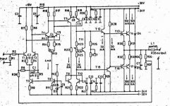
OK, what about this ?
There are 2 differential, T1 and T2 is differential, again differentiated by T4 and T5. T7 and T8 are VAS, T9 and T10 are current mirror.
This is dual differential, right?
There is also more complex design, Complementari differential + dual differential, where T1+T2 has its PNP friends, T3+T4 and T7+T8 also have their PNP friends. This design has 4 differential and 2 VAS pairs, like this attachment mirrored vertically.
AKSA, could you tell a little, why you never find it right with complementary differential? J Curl insisted on complementary differential, but he always uses Jfets+stacked self-biasing. Never tell about bipolar complementary differential+ordinary ccs.
Attachments
I don't know what D1,D2,D3 is.These aren't normal diode.I think I can never buy these.The image is too big.Can you convert it to jpg?Post #257
New idea: dual differential +complementation=dual complemetary differential .
Attachments
- Status
- Not open for further replies.
- Home
- Amplifiers
- Solid State
- Single or dual differential?