Peter Daniel said:I noticed that occasionally they are inactive, but check later, they'll work fine.
Maybe like Vishay's websites. They seem to be operational about 40% of the time. I think they turn their servers off at night (US time). Haven't ran into many sites like theirs.
JF
Ya Mon ! 2 stages is Enough !
The 2SJ200/2SK1529 power amplifier which challenges to the limit of 2 stage constitution
[ 1 ] First experimental circuit Generally, the power amplifier, e.g., the first level, the drive step and the output step, furthermore the source follower enters foreward the output step with, is formed with the stage of 3 steps or more, but it can estimate the deterioration of the extent sound where this stage numbers are few that it decreases.
With the experiment which is developed here, the amplifying stage of the past design absolutely necessity?, you try probably to take a second look whether the efficiency which that brings essentially is important.
Fundamental reformation is necessary in restructuring of amplifier constitution, but well is, when like this is, rather than expressing theoretical empty theory, as I of practice principle, as for here even if it is not possible with the meaning be no other choice but to it tries making the amplifier where with you can obtain sufficient efficiency the less stage number and, it just is found, the ‚Ä something topic you think that perhaps, the new road opens with the calling and the theme which derives from there.
[ 2 ] Revised circuit
[ 3 ]Crss symmetrization circuit
[ 4 ]Emitter follower drive addition
[ 5 ] The first level FET multiple connection
[ 6 ] Output step source follower/overall NFB
[ 7 ]The output step source follower/there is no overall return
[ 8 ] The first level circuit
[ 9 ] ƒJƒvƒŠƒI ƒNƒAƒbƒh circuit
[ 10 ]The PP circuit which utilizes the opposite quality of MOS-FET
[ 11 ] Experiment of intersection type output circuit
[ 12 ] Revised edition voltage amplification circuit
[ 13 ]2SJ200/2SK1529 power amplifier 1st number
[ 14 ]2SJ200/2SK1529 power amplifier 1 reforming
[ 15 ]About 2SJ200/2SK1529
[ 16 ]2SJ200/2SK1529 voltage mirror
[ 17 ]2SK2313 Kanada system
[ 18 ] Invertedtype
[ 19 ] The first level reforming inverted type
[ 20 ] Decrease return source follower inverted type
[ 21 ] ZD level shift system NFB type
[ 22 ] ZD level shift system non return type
Re: Ya Mon ! 2 stages is Enough !
Watch out, thought I saw some NFB stuff there. Might be contagious.
Borbely's super buffer and all FET line amp (figs. 7-9) also seem instructive (at least to me):
http://www.borbelyaudio.com/borb502.pdf
JF
hitsware said:The 2SJ200/2SK1529 power amplifier which challenges to the limit of 2 stage constitution
...
Watch out, thought I saw some NFB stuff there. Might be contagious.
Borbely's super buffer and all FET line amp (figs. 7-9) also seem instructive (at least to me):
http://www.borbelyaudio.com/borb502.pdf
JF
>Watch out, thought I saw some NFB stuff there. Might be contagious.
For a common drain (output stage(sorta attractive for swinging up (and down)to the rails)) I don't have a way to do 0 feedback (short using xfmrs) .......... any ideas ?
For a common drain (output stage(sorta attractive for swinging up (and down)to the rails)) I don't have a way to do 0 feedback (short using xfmrs) .......... any ideas ?
Re: Ya Mon ! 2 stages is Enough !
So you're the guy who writes all the owners manuals for Japanese electronics? 😀
se
hitsware said:The 2SJ200/2SK1529 power amplifier which challenges to the limit of 2 stage constitution
[ 1 ] First experimental circuit Generally, the power amplifier, e.g., the first level, the drive step and the output step, furthermore the source follower enters foreward the output step with, is formed with the stage of 3 steps or more, but it can estimate the deterioration of the extent sound where this stage numbers are few that it decreases.
With the experiment which is developed here, the amplifying stage of the past design absolutely necessity?, you try probably to take a second look whether the efficiency which that brings essentially is important.
Fundamental reformation is necessary in restructuring of amplifier constitution, but well is, when like this is, rather than expressing theoretical empty theory, as I of practice principle, as for here even if it is not possible with the meaning be no other choice but to it tries making the amplifier where with you can obtain sufficient efficiency the less stage number and, it just is found, the ‚Ä something topic you think that perhaps, the new road opens with the calling and the theme which derives from there.
So you're the guy who writes all the owners manuals for Japanese electronics? 😀
se
hitsware said:>Watch out, thought I saw some NFB stuff there. Might be contagious.
For a common drain (output stage(sorta attractive for swinging up (and down)to the rails)) I don't have a way to do 0 feedback (short using xfmrs) .......... any ideas ?
Why stop short of using transformers?
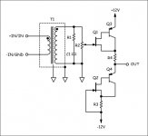
How 'bout something like this:
Attachments
Steve Eddy said:
Why stop short of using transformers?
How 'bout something like this:
OK ....... Do you have a description of exactly how your circuit operates .... The bottom half is particularily non evedent to me.
........mike 🙂
hitsware said:OK ....... Do you have a description of exactly how your circuit operates .... The bottom half is particularily non evedent to me.
........mike 🙂
Sure. The transformer provides the circuit's voltage gain. R1 and C1 are a damping network for that particular transformer, giving it a smooth Bessel rolloff. R2 doubles as the transformer's secondary load as well as volume control. The output is a JFET/bipolar Sziklai pair (a complimentary version of the Darlington pair) used as a voltage follower. The bottom half is the same pair used as a current source.
se
how do you get a 'current source' off of the emitter of a xsistor?
i have a tendancy to think of emitters as 'voltage sources'
i have a tendancy to think of emitters as 'voltage sources'
hitsware said:how do you get a 'current source' off of the emitter of a xsistor?
i have a tendancy to think of emitters as 'voltage sources'
Because that PNP bipolar ultimately behaves as an NPN. Or perhaps more accurately, the pair behaves like a single N-type device. Look up "Sziklai pair" or "complimentary feedback pair" or "complimentary Darlington."
se
>So you're the guy who writes all the owners manuals for Japanese electronics?
Ya Mon .... Me new gig ! ..... Ain't computers wonderfull ? 🙂
Ya Mon .... Me new gig ! ..... Ain't computers wonderfull ? 🙂
hitsware said:>So you're the guy who writes all the owners manuals for Japanese electronics?
Ya Mon .... Me new gig ! ..... Ain't computers wonderfull ? 🙂
Yeah, when they're not busy being evil incarnate. 🙂
se
Steve Eddy said:
Because that PNP bipolar ultimately behaves as an NPN. Or perhaps more accurately, the pair behaves like a single N-type device. Look up "Sziklai pair" or "complimentary feedback pair" or "complimentary Darlington."
se
Yea...OK..sorta got it. Would there be a way to bootstrap the CS 'dynamic class A' ?
hitsware said:
Yea...OK..sorta got it. Would there be a way to bootstrap the CS 'dynamic class A' ?
I suppose. But why make it more complicated? Not too many posts ago you were advocating using the parasitic input capacitance of a FET in order to keep things simple and avoid having to use a literal capacitor. What happened to that guy? 🙂
By the way, came across a quote by Antoine de Saint-Exupéry a while back you might enjoy:
"Perfection is attained not when nothing more can be added, but when nothing more can be taken away."
se
Sirs,
I am sorry but I do not understand. So many posts talking about inherently very poor circuit designs (horrible THD and IMD, high output impedance, low linearity, low power). Simple does not necessarily mean very poor, but most of the circuits shown here do. What's the reason? Just for fun? 😉
I am sorry but I do not understand. So many posts talking about inherently very poor circuit designs (horrible THD and IMD, high output impedance, low linearity, low power). Simple does not necessarily mean very poor, but most of the circuits shown here do. What's the reason? Just for fun? 😉
PMA said:I am sorry but I do not understand. So many posts talking about inherently very poor circuit designs (horrible THD and IMD, high output impedance, low linearity, low power). Simple does not necessarily mean very poor, but most of the circuits shown here do. What's the reason? Just for fun? 😉
You mean like this one? 😀
An externally hosted image should be here but it was not working when we last tested it.
se
- Status
- Not open for further replies.
- Home
- Amplifiers
- Solid State
- Single or dual differential?