Non-feedback class AB? There must be a Gm doubling area (i.e. for smaller output voltages the gain is different than for higher output voltages, resulting in a kind of cross-over distortion).
Ducks?
Ducks???

john curl said:Folks, please get your ducks in a row about this circuit.
Ducks???
Re: The hard way....is the best way 🙂
Perhaps my QC is a little laxer than yours. I look for fairly symetrical clipping and leave it at that. AND I'm not doing any quantities, so I'll continue this way. I do not like trimpots.
I can always take the rejects from 1 amp and adjust (fixed) resistors on the next and recycle that way. So far this method works for me, but thanks for the input...........mike
Fred Dieckmann said:"I think perhaps we're both saying the same thing from differant points in the design cycle.........mike"
No we are not. You are have to sort through a lot of jfets to find a specific Idss.
Matching a couple Jfets for Idss greater than the desired bias current value and putting a trim pot to select to desired current is so much easier, that this is a no brainer. Sort a through few dozen Jfets to find a specific value and you will find out the hard way.......
Perhaps my QC is a little laxer than yours. I look for fairly symetrical clipping and leave it at that. AND I'm not doing any quantities, so I'll continue this way. I do not like trimpots.
I can always take the rejects from 1 amp and adjust (fixed) resistors on the next and recycle that way. So far this method works for me, but thanks for the input...........mike
PMA said:Non-feedback class AB? There must be a Gm doubling area (i.e. for smaller output voltages the gain is different than for higher output voltages, resulting in a kind of cross-over distortion).
Yes, but it specs OK (for me) and sounds delightfull. The lack of feedback does something magical that swamps out any other shortcomings (IMO) ....... I'm surprised no one has mentioned the output capacitor ..... A bone of contention for many 🙂
> I still think that a gate resistor of maybe the 100 ohm to 1K is not a bad idea
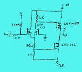
The circuit which brought-out this side-discussion has a 390Ω impedance at the Gate.
If you can build it compact, with Gate very-close to that resistor, there's no need for an added resistor.
If you can't build it compact, you are liable to more troubles than a simple stopper can cure.
> Voicing the sound of tube circuits by the value of the grid resistor is a pretty well know design trick.
Yes, in part because R-C coupling tends to overload badly. Adding a few K of resistance in the Grid has little impact on the undistorted sound but a major effect on overload behavior for highly transient signals (speech/music). Adding grid resistance also lowers HF gain or feedback, which is a "voicing".
> I find that well damped circuits at RF frequencies often sound better and more consistent.
This may be true. I would wonder though why any RF is running around my circuit. Perhaps it has stability or shielding problems, and perhaps fixing that would be a better path. Yes, RF stability is a real dark hole for most audio designers, who must either schedule a second career in RF engineering or just apply band-aids.
> I think these values shouldn't have too much effect on line level and power amps noise figures.
Agreed. Some, since we know the ear is a pretty sensitive organ. But not a lot, and generally lost in the haze of other noise sources. (Preamp design is different.) And as you note, a typical JFET has more noise than a 1K resistor (which figures, considering its Gm).
In large power MOSFETs, Gate resistance is provably bad. See Pass's notes on Zen amps: the Gate capacitance is large and non-linear, and a few K of Gate resistance can make distortion rise several percent in the top of the audio band. Small JFETs have this effect, but much-much less, and a K or two is probably not going to be your biggest distortion source.
> has to be selected, but selected for what?
As noted, so bias current for V-LED/2 is appropriate and reasonable.
In Mass Production, that is intolerable. Who has time to sort and label production parts, much less stock sorted spare parts and deal with home-repairs using the "right" part but not properly selected? Even selecting or trimming source resistors is a pain. I remember bad old days like that, and I am glad they are gone.
For home-brew, or high-price boutique gear, selection can give "better" results than robust use-any-part design. It does mean more hassle in building and repairing, so you better be sure the results are worth it. For many people here, it probably is (unless you have to buy 20 parts to get 2 that work as hoped).
I have nothing against non-global feedback amps (you will find one of them, class A, on my web pages). But I do prefer lower distortion and higher damping factor, and higher output power as well 😉
Pavel
Pavel
would adding a 9.5k between the 2nd input and ground be a good idea? (matching the input impedances)
Bricolo said:would adding a 9.5k between the 2nd input and ground be a good idea? (matching the input impedances)
A little maybe but with mosfets (no bias current) don't make much differance..
Bricolo said:is it only usefull for bipolars?
With bipolars it balances the pair offsetwise. With fets that's not a problem, but there may be some dynamic considerations. Perhaps someone with better understanding will chime in here.
I would use it.
After all, it's only one more resistor. And when designing the PCB, it could even make things simplier in some situations. You don't have to make the ground trace go to the 2nd gate, take a resistor to connect the gate to ground 🙂
After all, it's only one more resistor. And when designing the PCB, it could even make things simplier in some situations. You don't have to make the ground trace go to the 2nd gate, take a resistor to connect the gate to ground 🙂
Fred, originally proposed a sophisicated and 'improved' biasing stage. I felt that it was not a 'universal' schematic, because it lacked placement of a source degeneration resistor in the N channel rail. However, Fred is correct in this one specific case with using J109's and K389's. Thanks Fred, I didn't notice the difference between Gm's before, in these two devices. However, if you were using K170's and J75's, the difference would be less, and almost unmeasurable. Personally, in a simple circuit like this, I prefer to use high Idss types and run them as hard as possible. This includes even slightly overbiasing the input devices in the forward direction, under transient peaks. Please think it through, before attacking my comment.
As pointed before, I looked at http://www.ne.jp/asahi/evo/amp/J200K1529/report.htm and find many "not-ordinary" designs there. Are they practical design, or just design idea? Has someone have a chat with those Japanese designer, I think they have different spirit about audio amplifier from person like Mr.Pass or Mr.JC.
I learned that Mr.JC is former designer of MarkLevinson. Could anyone give me a brief schematic of what is inside MarkLevinson Ref.No.33 (The 200kg mono power amp)? Does it uses basic schematic like Ref.no.2 or JC-3?
I learned that Mr.JC is former designer of MarkLevinson. Could anyone give me a brief schematic of what is inside MarkLevinson Ref.No.33 (The 200kg mono power amp)? Does it uses basic schematic like Ref.no.2 or JC-3?
I believe that Mr.Curl did not design the Ref.33.
The Ref.33 is not a complementary design and nowhere as elegant as Mr.Curl's work. It looks more like a parts farm, to quote another member of this forum.
Regards,
Jam
The Ref.33 is not a complementary design and nowhere as elegant as Mr.Curl's work. It looks more like a parts farm, to quote another member of this forum.
Regards,
Jam
Check this link to _see_ what'sinside ref 33. http://www.marklevinson.com/image_library/index.asp?categoryID=6&productID=12
Use this link for technical overview http://www.marklevinson.com/products/overview.asp?cat=pa&prod=no33h
Use this link for technical overview http://www.marklevinson.com/products/overview.asp?cat=pa&prod=no33h
Peter Daniel said:Check this link to _see_ what'sinside ref 33. http://www.marklevinson.com/image_library/index.asp?categoryID=6&productID=12
The outside certainly *looks* impressive. The "what's inside" pics seem to be dead currently.
JF
I noticed that occasionally they are inactive, but check later, they'll work fine. Those are high res pics, showing even the print on ICs.
I know that some guys don't like ML, but I was always impressed with their engineering. So recently, I bought myself ML38 preamp board. At $140 it seemed hard to refuse. Finally, I have a piece of a cake too.😉
I know that some guys don't like ML, but I was always impressed with their engineering. So recently, I bought myself ML38 preamp board. At $140 it seemed hard to refuse. Finally, I have a piece of a cake too.😉
- Status
- Not open for further replies.
- Home
- Amplifiers
- Solid State
- Single or dual differential?