....Bricolo said:
what scematic are you talking about?
Attachments
PMA said:I am sorry I meant 10kHz - 20kHz, as THD is usually worse at higher frequencies.
I don't remember if I did 20k but did do 10k (don't have the analyzer any more). Also (and I think importantly) the distortion was ~same at all levels........mike
PMA said:Pretty confusion - I was speaking about image at Post No.81.
That one is in the conceptual stage. Should sound good though. 🙂
PMA said:Pretty confusion - I was speaking about image at Post No.81.
http://www.ne.jp/asahi/evo/amp/J200K1529/report.htm
Oops ....... Somebody did it .....
hitsware said:
....
The 2SK170 has to be selected, but selected for what? I don't see the reason for it, there's no "matching" required (no dif pair, no multiple output transistors...)
Bricolo said:
The 2SK170 has to be selected, but selected for what? I don't see the reason for it, there's no "matching" required (no dif pair, no multiple output transistors...)
To have it run in the center of it's operating range with the given resistor values.............jfets do vary somewhat
> I thought that dif pairs had a very high gain.
Voltage gain to one output is one-half of the same device working grounded-cathode (or whatever).
On another forum I just pointed out that if you have two triodes, cascading them gives 2*Mu more voltage gain than the same tubes as a diff-pair.
Diff-pairs are useful in high-gain DC amplifiers because the diff-pair has near-zero DC offset. They are often useful in audio with NFB because you get two "identical" inputs. They also avoid cathode bypass capacitors which are often problematic.
The diff-pair has half the gain of a single device, but using BJT, Pentodes, or cascoded FETs or Triodes the useful gain is really limited by stray leakage and capacitance, and may be further limited by overall NFB stability consideration.
If you take both outputs of a diff-pair (either two outputs or a current-mirror turn-around), the gain is identical to a single device.
Tail wagging the dog
"To have it run in the center of it's operating range with the given resistor values.."
Vary the resistor values. Go read
http://www.borbelyaudio.com/ae599bor.pdf
http://www.borbelyaudio.com/ae699bor.pdf
and learn to bias jfets.
"To have it run in the center of it's operating range with the given resistor values.."
Vary the resistor values. Go read
http://www.borbelyaudio.com/ae599bor.pdf
http://www.borbelyaudio.com/ae699bor.pdf
and learn to bias jfets.
Folks, please get your ducks in a row about this circuit.
Personally I don't like to use much series resistance in the base of Jfets, BECAUSE it increases the noise of the entire unit. SE is correct, if you want to make an input filter, then put 50-200pf mica or film cap to ground to have a LINEAR capacitance at the jfet input. Then you can reduce the input R to 1K or so.
Personally I don't like to use much series resistance in the base of Jfets, BECAUSE it increases the noise of the entire unit. SE is correct, if you want to make an input filter, then put 50-200pf mica or film cap to ground to have a LINEAR capacitance at the jfet input. Then you can reduce the input R to 1K or so.
PRR said:> I thought that dif pairs had a very high gain.
Voltage gain to one output is one-half of the same device working grounded-cathode (or whatever).
On another forum I just pointed out that if you have two triodes, cascading them gives 2*Mu more voltage gain than the same tubes as a diff-pair.
Diff-pairs are useful in high-gain DC amplifiers because the diff-pair has near-zero DC offset. They are often useful in audio with NFB because you get two "identical" inputs. They also avoid cathode bypass capacitors which are often problematic.
The diff-pair has half the gain of a single device, but using BJT, Pentodes, or cascoded FETs or Triodes the useful gain is really limited by stray leakage and capacitance, and may be further limited by overall NFB stability consideration.
If you take both outputs of a diff-pair (either two outputs or a current-mirror turn-around), the gain is identical to a single device.
Understood.
Thanks for the explanations 😉
Re: Tail wagging the dog
To maintain the simplicity of the circuit (keeping the gain, Iq, etc. equal without the use of source resistor bypass caps) it seems a better approach to me to select jfets. IMO
Fred Dieckmann said:"To have it run in the center of it's operating range with the given resistor values.."
Vary the resistor values. Go read
http://www.borbelyaudio.com/ae599bor.pdf
http://www.borbelyaudio.com/ae699bor.pdf
and learn to bias jfets.
To maintain the simplicity of the circuit (keeping the gain, Iq, etc. equal without the use of source resistor bypass caps) it seems a better approach to me to select jfets. IMO
john curl said:Folks, please get your ducks in a row about this circuit.
Personally I don't like to use much series resistance in the base of Jfets, BECAUSE it increases the noise of the entire unit. SE is correct, if you want to make an input filter, then put 50-200pf mica or film cap to ground to have a LINEAR capacitance at the jfet input. Then you can reduce the input R to 1K or so.
Input noted and appreciated 🙂
Re: Tail wagging the dog
You might want to revue that article yourself. (Thanks🙂 )
He suggests selecting devices.............mike
Fred Dieckmann said:"To have it run in the center of it's operating range with the given resistor values.."
Vary the resistor values. Go read
http://www.borbelyaudio.com/ae599bor.pdf
http://www.borbelyaudio.com/ae699bor.pdf
and learn to bias jfets.
You might want to revue that article yourself. (Thanks🙂 )
He suggests selecting devices.............mike
"Personally I don't like to use much series resistance in the base of Jfets"
Don't you mean gate?
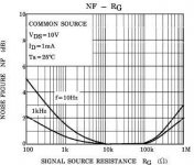
I also like to use input filters with the series resistor the value of the characteristic impedance of the interconnect. this filters RF and helps to terminate the interconnect at high frequencies. This obviously calls for the use low impedance drivers but eases the requirements on build out resistors. I still think that a gate resistor of maybe the 100 ohm to 1K is not a bad idea to damp out RF resonances between device capacitance and trace and wiring inductance. Voicing the sound of tube circuits by the value of the grid resistor is a pretty well know design trick. I find that well damped circuits at RF frequencies often sound better and more consistent. I think these values shouldn't have too much effect on line level and power amps noise figures. I remember a recent thread extolling the virtues of JFETs for low noise for moderately high source impedances. The Noise Figure graph for the 2SK389 shows the device noise starting to dominate the resistor noise for impedances below around a few thousand ohms if I am not mistaken.
Don't you mean gate?
I also like to use input filters with the series resistor the value of the characteristic impedance of the interconnect. this filters RF and helps to terminate the interconnect at high frequencies. This obviously calls for the use low impedance drivers but eases the requirements on build out resistors. I still think that a gate resistor of maybe the 100 ohm to 1K is not a bad idea to damp out RF resonances between device capacitance and trace and wiring inductance. Voicing the sound of tube circuits by the value of the grid resistor is a pretty well know design trick. I find that well damped circuits at RF frequencies often sound better and more consistent. I think these values shouldn't have too much effect on line level and power amps noise figures. I remember a recent thread extolling the virtues of JFETs for low noise for moderately high source impedances. The Noise Figure graph for the 2SK389 shows the device noise starting to dominate the resistor noise for impedances below around a few thousand ohms if I am not mistaken.
Attachments
"He suggests selecting devices.............mike"
I select devices too, but you have know what you selecting for. To get a specific
value of quiesent current, you have to adjust the source resisitor. I think if you measure a handful of Jfets from the same bias group (GR BL or V) you will be suprised at the variations in Idss.
I select devices too, but you have know what you selecting for. To get a specific
value of quiesent current, you have to adjust the source resisitor. I think if you measure a handful of Jfets from the same bias group (GR BL or V) you will be suprised at the variations in Idss.
Fred Dieckmann said:"He suggests selecting devices.............mike"
I select devices too, but you have know what you selecting for. To get a specific
value of quiesent current, you have to adjust the source resisitor. I think if you measure a handful of Jfets from the same bias group (GR BL or V) you will be suprised at the variations in Idss.
With a given source resistor, load resistor, and PS, Iq can be matched simply by substituting devices until the (standard (of your choice)) quiessent drain voltage is attained. I think perhaps we're both saying the same thing from differant points in the design cycle.........mike
Mike, tell me, what is the Vgs voltage of the Mosfets. Usually about 4V, isn't it? And they are biased by "large green LED diode" in your schematics, is it correct?
PMA said:Mike, tell me, what is the Vgs voltage of the Mosfets. Usually about 4V, isn't it? And they are biased by "large green LED diode" in your schematics, is it correct?
These (lateral) mosfets have a much lower threshold voltage than the IR types. The led has ~1.65 volts forward voltage, so each output sees ~0.8 V 'enhancement'. Not class A, but a nice warm AB. ~160ma.
The hard way.........
"I think perhaps we're both saying the same thing from differant points in the design cycle.........mike"
No we are not. You are have to sort through a lot of jfets to find a specific Idss.
Matching a couple Jfets for Idss greater than the desired bias current value and putting a trim pot to select to desired current is so much easier, that this is a no brainer. Sort a through few dozen Jfets to find a specific value and you will find out the hard way.......
- Status
- Not open for further replies.
- Home
- Amplifiers
- Solid State
- Single or dual differential?