What went wrong in the beginning? I assumed that, like the diagrams showing the base connection of the transistor was the middle pin. It was not, according to the datasheet, the 13001 has an E-C-B pin layout.
Some notes on changes to the circuit: the input capacitor is a 470 uF that makes a slight difference to the output. The 2k Ohm resistor was actually a variable resistor, carefully adjusted to around 2k. There were no other changes to the circuit.
Sound was measured at 50 dB at 10 cm from 4 Ohm speaker without the amplifier, that is, direct PC headphone output to speaker. With the amplifier the output went up to 60 dB at 10 cm.
The sound is fairly clear at low volumes, and using the PC software volume boost at greater than 100% improved things quite a bit. The music player matters - Audacity with bass controls was best, followed by the Clementine music player.
Right now I am listening to my favourite songs, and two things come to mind:
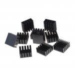
The transistor is too hot to touch. Do I need a heat sink?
As someone suggested, I checked the battery, and it is putting out an healthy 8 Volts, this for a 9 Volt battery. I can go up-to 12 V or use a power adapter but heat damage is a real concern.
My first class A amplifier ! Just to get it to work is good enough.
Some notes on changes to the circuit: the input capacitor is a 470 uF that makes a slight difference to the output. The 2k Ohm resistor was actually a variable resistor, carefully adjusted to around 2k. There were no other changes to the circuit.
Sound was measured at 50 dB at 10 cm from 4 Ohm speaker without the amplifier, that is, direct PC headphone output to speaker. With the amplifier the output went up to 60 dB at 10 cm.
The sound is fairly clear at low volumes, and using the PC software volume boost at greater than 100% improved things quite a bit. The music player matters - Audacity with bass controls was best, followed by the Clementine music player.
Right now I am listening to my favourite songs, and two things come to mind:
The transistor is too hot to touch. Do I need a heat sink?
As someone suggested, I checked the battery, and it is putting out an healthy 8 Volts, this for a 9 Volt battery. I can go up-to 12 V or use a power adapter but heat damage is a real concern.
My first class A amplifier ! Just to get it to work is good enough.
Image
Images
The battery is getting warm and also is down to 4 Volts in operation. Running off USB power is not an option I suppose due to the high power draw.
Current draw is 0.09 Amps that is 90 Milliamps. Voltage base to emitter is 0.8 V.
The data sheet lists 400V as input voltage (max) and 150C junction temperature, which seems to mean we do not need a heat sink.
Attachments
Last edited:
The transistor is too hot to touch. Do I need a heat sink?
My first class A amplifier
Class A amplifiers run hot.
Yes. You need a heatsink if you want it to last!!
Could you suggest a heat sink apart from making my own? There seem to be no heatsinks for small transistors.
DIY Heatsink for Small Transistors : 6 Steps (with Pictures) - Instructables
DIY Heatsink for Small Transistors : 6 Steps (with Pictures) - Instructables
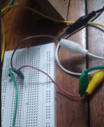
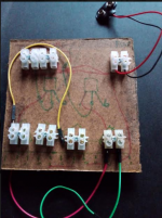
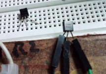
For a start, connecting the components using a solderless connector system. This is just a rough prototype:
Updates at this site:
Updates at this site:
Attachments
Last edited:
The thing is working now, with its rough and ready state. Many questions arise. Right now it is running off approximately 5 Volts which does not help distortion. Gain is adjustable via a variable resistor across emitter and base, adjusted for minimum distortion.
I want to fix a variable resistor the type you can adjust via a screwdriver to have an adjustable gain. Is this a good idea? Also, I plan to split a 12 V supply and run both left and right channels off the same power source. Any problems with this, and it will be a AC/DC converter for power.
The input capacitor is now a 10 uF one. The speakers can go from about 95 to 13,000 Hz. This means I should use a capacitor as a high pass filter to remove the frequencies below 100 Hz or so? Which means a capacitor of what?
Last edited:
9V converted AC more or less settles it. The transistor gets very hot, nothing to do but attach the heatsink and take my chances. Using less Volts means less heat, so maybe there is a compromise. A cooling fan is an attractive option under these circumstances - my laptop has it for example.
Changing the input capacitor to 2.2 uF helped cut out much of the distortion. The rest of the work was done with Audacity bass and treble adjustments to obtain acceptable volume and clarity. This with a new 9V battery.
I know what you are thinking. All this work when a good chip amp would give better sound at a lower cost and efficiency. Maybe time to look at the speakers. More testing to check if it is worth creating a case for this.
Attachments
Testing with different speakers
Testing
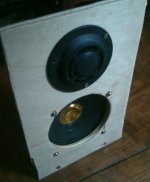
Testing with this speaker or a very similar one did produce sound that was listenable. although very soft in volume. Simply not enough power to drive those, but demonstrates that the circuit could be used with larger speakers.
SONY SS-G333ESの仕様 ソニー
This system is very sensitive to the volume of the input file, some mp3 files are show clipping throughout on Audacity. Some play softly. Overall better than PC speakers.
Testing with my Desktop Open Baffles was disappointing, hardly any sound to listen to. That consists of a woofer and tweeter with only a capacitor on the tweeter.
Testing
Testing with this speaker or a very similar one did produce sound that was listenable. although very soft in volume. Simply not enough power to drive those, but demonstrates that the circuit could be used with larger speakers.
SONY SS-G333ESの仕様 ソニー
This system is very sensitive to the volume of the input file, some mp3 files are show clipping throughout on Audacity. Some play softly. Overall better than PC speakers.
Testing with my Desktop Open Baffles was disappointing, hardly any sound to listen to. That consists of a woofer and tweeter with only a capacitor on the tweeter.
Attachments
Last edited:
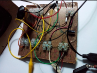
Switched Transistor to C945
Replaced Transistor
The 13001 transistor was replaced with a C 945 by simply removing the old transistor and inserting the new one into the makeshift holder. It was a case of plug and play, and it works fine. So now I have the transistor for the second channel of the amplifier.
Replaced Transistor
The 13001 transistor was replaced with a C 945 by simply removing the old transistor and inserting the new one into the makeshift holder. It was a case of plug and play, and it works fine. So now I have the transistor for the second channel of the amplifier.
Attachments
I the circuit below, the speaker is connected directly to the DC power supply. I noticed when testing with a larger speaker, the speaker cone changes its position based on the gain in the circuit. It appears to be good practice to 'keep DC out of the speaker', however I am not sure how to achieve this - a capacitor in series with the speaker cuts out all sound to the speaker.
Circuit:
https://theorycircuit.com/wp-conten...single-transistor-audio-amplifier-circuit.png
This circuit uses a 4.7 F capacitor and a microfarad capacitor in parallel. Is this a good idea?
DIY Class-A 2SK1058 MOSFET Amplifier Project
Circuit:
https://theorycircuit.com/wp-conten...single-transistor-audio-amplifier-circuit.png
This circuit uses a 4.7 F capacitor and a microfarad capacitor in parallel. Is this a good idea?
DIY Class-A 2SK1058 MOSFET Amplifier Project
Last edited:
The circuit you are using is only a very basic one and is not HiFi !
You have reached the limits of the circuit and should now consider another.
You could use the FET circuit ( or even adapt your circuit ) but you would be wasting half the power in the 15ohm resistor (plus heat).
The classic way to keep the voltage out of the LS is to use an output transformer.
Audio Transformer 1300 : 8 Ohm EE14 Output Transformer UK Seller | eBay
EAGLE LT700 MINIATURE OUTPUT MATCHING TRANSFORMER. PRIMARY 1K2 SEC 3R2 5021196036975 | eBay
Andy
Last edited:
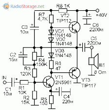
Scheme # 37. The efficiency is 10%. 1 watt output, 10 watts consumed. You need a good power source.
Large battery, linear network or SMPS (from a laptop). Average power transistor TO220, better darlington 🙂
You can build the Hood1969 amplifier klass A.
Large battery, linear network or SMPS (from a laptop). Average power transistor TO220, better darlington 🙂
You can build the Hood1969 amplifier klass A.
Output transformer? Yes I have seen this in a video, but I was afraid of that because of its sheer bulk. I have such a transformer from my salvaged PC speaker power section, so I guess I could try that out. I will need two. Will be impressively heavy though.
A substituted the 9 Volt battery that was anyway giving out 4 Volts, and did not use a new 9 V which was basically burning up my transistor, settled for a bank of 4 AA batteries giving 6 V maximum, so everything is better - sound is louder before distorting, and the power lasts longer - 1000 mAh vs 400 mAh or so.
I have to design my case and the heat sink - which will consist of washers mounted on a bolt - should look impressive. Right now the washer does not get too hot to touch.
It might not sound great, but it is my amplifier - I like a child, you would not care how he sounds. I know, it I am biased (pun intended).
Thanks. I just assumed. I think I have some in my components box. What will be the effect on sound? right now I am listening to the thing and it is fine. Good detail.
The suggested
So, maybe as a next project, then this seems to be a good project. 5-12 Volts is a great range.
Is this the one? Any equivalents?
https://www.amazon.com/Transistors-silicon-military-KT805B-analogue/dp/B00J4H6ZYA
The diagram of the emitter follower is shown. The load is included in the emitter. The input voltage must exceed the operating voltage of the LED by 0.7V (Vbe).
Any (almost) general purpose transistor will do. For noticeable power (current), a transistor in a TO-126 or TO-220 package is needed.
Простейший усилитель звука на одном транзисторе за 15 минут
So, maybe as a next project, then this seems to be a good project. 5-12 Volts is a great range.
Is this the one? Any equivalents?
https://www.amazon.com/Transistors-silicon-military-KT805B-analogue/dp/B00J4H6ZYA
Yes! But there is a modern version in the TO-220 case. You can use transistors TIP, BD, BU from the dismantling of electronic scrap or from Aliexpress for c50. Darlington transistors (TIP102-127) are suitable.
The Lin amplifier has a first voltage amplification stage and a follower.
The Lin amplifier has a first voltage amplification stage and a follower.
Last edited:
- Home
- Amplifiers
- Solid State
- Single gain stage transistor amplifier.