The IXTN90P20P is a bit different from the IXTN40P50P. Try increasing R4 (3k) to 8k. That should lower the current if the circuit is functioning properly.
Again thank you Ben.
Replaced R4 with 10K as it was handy.
My understand is Vgs is the voltage across gate-source. Red lead on Gate and black on Source with the DBT in, the vo;tage slowly climbs to about -0.8V, I didn't let it run too long but only the 0.1mV was still climbing. Just to see I did a quick test with the DBT out and same test the Gate to Source voltage was +0.9, but the short time it was on it looked pretty stable. I have a switch on my DBT that lets me bypass the bulb, so this test was only a couple of seconds.
Still adjusting R3 doesn't have an effect.
So just to be crazy, I replace the IXTN90P20P with a IRF9240, still using the DBT. I was again limited to around 1.5A by the DBT but the bulb acted very different. With the IXTN part the bulb burns bright as the caps are charging, but then continues to burn bright. With the 9240 the bulb burns bright for cap charging and then dims to almost out as no current is flowing, then the current starts to come up and the bulb is bright again. I'm getting more suspect thatIXTN parts are no good.
So getting bolder with the 9240, I bypassed the bulb... current rose to 2.2A (R4 still at 10K)
Seems much more resonable than the +5A I was seeing without the DBT using the IXTN part. I aslo never felt any heat in the IXTN parts during testing, but the 9240 is definetly getting warm. Gate to Source voltage using the 9240 was about -5.5V and seemed pretty steady, although I never let it run long.
At the moment I am considering the IXTN parts bad.
Any additional thoughts from your side?
G
You can check the IXTN parts with a multimeter. Do an internet search for testing P channel mosfet with a multimeter.
The positive value of Vgs is not normal. That could indicate too much current at the mosfet gate of the IXTN, a sign of a bad mosfet, or possibly an issue with the optocoupler. Assuming all of the resistor values are correct and the capacitor at the optocoupler is working properly, there are no other parts that could go wrong.
Does adjusting the trimmer when the IRF is in place change the current? Even with the DBT in place, the current should change with the trimmer adjustment. The trimmer changes the Vgs of the mosfet which in turn should change the current through it.
When switching between DBT and no DBT, set trimmer to maximum resistance (minimum current) before switching to no DBT.
Last edited:
Ben,
I already applied for a refund on the mosfets as today was the last day to return them. Ordered some 40P50P
With the irf installed I still don’t see a change in vgs with a change in the pot.
I finished the other channel, this still has R4 at 3K, I get the same behavior for this channel.
so I’m a bit stumped.
mosfet Vgs -5.6V (irf)
with DBT about 1.4A
remove DBT about 2.2A
power meter on the wall shows 75W with the DBT and 150W without the DBT
I think it might be best to wait until the 40P50P parts come and try again.
thanks again,
G
I haven't measured the mosfet Vgs on my amps since adjusting the trimmer varied the current. Did you measure the current as you adjusted the trimmer with the IRF in place? I just did a check on LTSpice and adjusting the trimmer only changed Vgs a small amount but the current did change.
The current of2.2A without DBT is promising. Adjust the trimmer and see if the current changes.
The current of2.2A without DBT is promising. Adjust the trimmer and see if the current changes.
Hi Ben,
The current does vary from about 2.1A at one end of the trimmer to about 2.5A, at the other end. (I know you mentioned not to bypass the DBT at the low end of the trimmer, but it was for only about 1sec.)
G
The current does vary from about 2.1A at one end of the trimmer to about 2.5A, at the other end. (I know you mentioned not to bypass the DBT at the low end of the trimmer, but it was for only about 1sec.)
G
That is high praise from one whose opinion I hold in the highest regard.I use NP's DIY FE 2022 as a preamp/front end for all of my follower amps and it's a great front end.
Considering some of the exotica you have used in the past ...
Hope all is well for you.
Take care,

Well, that is my opinion. In my system it sounds great. I have stated this quite a few times now but for me, the clarity of the high end improved with the drop in distortion. The dominant harmonic is still second.
So common drain amplifier over common source dropped the distortion a large amount. Then the DIY FE 2022 replacing my 2SK79 preamp dropped the distortion some more.
I started out with higher amounts of second harmonic distortion with single ended tube amps and preamp, then went to common drain VFET/SIT single ended amplifiers and preamps, then to single ended common drain amplifiers, and now to low second harmonic distortion preamp.
It has been a long journey. 🙂
That is very encouraging news since I would like to have a little added gain with my followers.
I know you are using the input module with much more gain than I would need.
Curious if you think the circuit would sound "good" with 5 to 7 dB of gain?
Thanks,
I know you are using the input module with much more gain than I would need.
Curious if you think the circuit would sound "good" with 5 to 7 dB of gain?
Thanks,
The gain of the DIY FE 2022 is adjustable with one resistor.
I have mine set up as a preamp/gain stage for all of my amplifiers so it is in its own chassis with power supply and volume control. But if you just use it as a dedicated gain stage for one amplifier, you can power it off the amplifier's power supply. It is very versatile. Then it would not cost much to give it a try.
I have mine set up as a preamp/gain stage for all of my amplifiers so it is in its own chassis with power supply and volume control. But if you just use it as a dedicated gain stage for one amplifier, you can power it off the amplifier's power supply. It is very versatile. Then it would not cost much to give it a try.
I keep missing the FE2022....last time it went up for sale at 3am and was sold out before I got up. I have a Mouser bag full of parts waiting for it.
Have options available.... Power it with +/- 32v Sigma 22 Power supply in a stand alone front end (Replacing BA3 Front End) .....or...... -64v in the Sit amps (I left a spot for them specifically).
I don't feel I'm lacking clarity but the comparison will be fun and easy enough.
Have options available.... Power it with +/- 32v Sigma 22 Power supply in a stand alone front end (Replacing BA3 Front End) .....or...... -64v in the Sit amps (I left a spot for them specifically).
I don't feel I'm lacking clarity but the comparison will be fun and easy enough.
It wasn't a case of me feeling a lack of clarity. I made changes and surprise, surprise, the highs got better and the music seemed more real. And that happened when I went from common source to common drain, and from preamps with higher amount of distortion to much lower distortion. I was not searching for clarity. It happened. 🙂
Since the circuit is basically an op amp I was wondering if, with low gains, the extra feedback made itself heard?
As I think about it it would probably be best to build it with more gain than I need and use a pair of resistors as an attenuator.
Now to meditate on whether to attenuate the input or the output ...
I put my name on the list - will see if I can respond quickly enough to get them when they become available.
HI Ben and All,
I'm hoping someone can help with a bit of teaching.
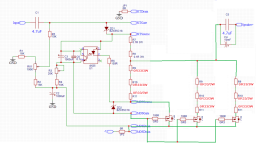
I've built Ben's curcuit with a slight modification, here is my modified version:

I haven't put music through it yet, but followed Ben's startup procedure and have 33V Vds across the SIT and I have the current adjusted to 2 amps, my target is to operate at 2.5 Amps.
I have done some google searching and some sites say MOSFET do a good job at current sharing but might be talking about when operated as a switch and not in the linear region. I have read that putting a balast resistor on the MOSFET can help current sharing, but I couldn't find a method of calculating the balast resistor and I am guessing it needs to be quite small value otherwise it will need to be rated for very large power disipation. I have mounted them in a delta pattern on the heatsink to try and adress this as well.
Am I using a little knowledge to make a big mistake?
Looking at the DS for the IRFP9240 and reading that the SOA is key for determining stability when operating in the linear region:

It would seem that even 1 9240 should be able to support it, although they don't show DC on the graph.
Then looking at power disipation in the DS it is 150W and a 1.2W/C linear derating.
I believe I need to disipate about 70W across these three MOSFET, do I not have enough safety margin?
On the practical side running for a limited time, all three MOSFETs heat up quite a bit as expected for this level.
I'm not looking to be spoon fed, more of an education.
Ben as the owner of this thread please let me know if this is off topic and I will ask for it to be removed.
G
I'm hoping someone can help with a bit of teaching.
I've built Ben's curcuit with a slight modification, here is my modified version:
I haven't put music through it yet, but followed Ben's startup procedure and have 33V Vds across the SIT and I have the current adjusted to 2 amps, my target is to operate at 2.5 Amps.
I have done some google searching and some sites say MOSFET do a good job at current sharing but might be talking about when operated as a switch and not in the linear region. I have read that putting a balast resistor on the MOSFET can help current sharing, but I couldn't find a method of calculating the balast resistor and I am guessing it needs to be quite small value otherwise it will need to be rated for very large power disipation. I have mounted them in a delta pattern on the heatsink to try and adress this as well.
Am I using a little knowledge to make a big mistake?
Looking at the DS for the IRFP9240 and reading that the SOA is key for determining stability when operating in the linear region:
It would seem that even 1 9240 should be able to support it, although they don't show DC on the graph.
Then looking at power disipation in the DS it is 150W and a 1.2W/C linear derating.
I believe I need to disipate about 70W across these three MOSFET, do I not have enough safety margin?
On the practical side running for a limited time, all three MOSFETs heat up quite a bit as expected for this level.
I'm not looking to be spoon fed, more of an education.
Ben as the owner of this thread please let me know if this is off topic and I will ask for it to be removed.
G
first - you need to have mosfet triplet matched by Ugs
then - if one mosfet schm is calling for 0R3 directly on source, to put triplet in place of one - you simply need to use source resistor of (0R3 * 3) for each one
that value coincidentally is more than enough to ensure proper current sharing
upper resistance in Mu follower chain stays 0R2
trick - R6 ( ref. to your schm above) must be connected just to one mosfet source
everything else stays the same
if you need visual help to grasp it, post or point to your fave complete schematic and I'll do editing
Zen Mod,
Great feedback.
Ugs is matched closely for all three.
Here is how my simple brain understood your advice:

Did I fully catch your point?
G
Great feedback.
Ugs is matched closely for all three.
Here is how my simple brain understood your advice:
Did I fully catch your point?
G
see
you can use 0R33/1W resistors, plenty of leeway there
if Iq being 2A5, means each string of 3 will get 2A5/3, means dissipated power in each 0R33 resistor is 0A83^2*0R33=230mW
don't forget bleeder resistor across speaker terminals; there is no one at schematic
you can use 0R33/1W resistors, plenty of leeway there
if Iq being 2A5, means each string of 3 will get 2A5/3, means dissipated power in each 0R33 resistor is 0A83^2*0R33=230mW
don't forget bleeder resistor across speaker terminals; there is no one at schematic
Attachments
Last edited:
Got it, many thanks. I missed this pointyou simply need to use source resistor of (0R3 * 3) for each one
G
- Home
- Amplifiers
- Pass Labs
- Single Ended Tokin SIT THF-51S Common Drain Mu Follower Amplifier, 45W?