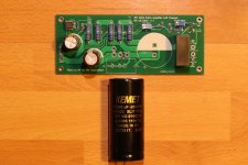
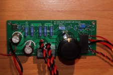
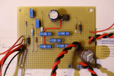
The left channel board is mostly stuffed. I have held off putting in the 10mF output capacitor though because it is huge, and I want to make sure it will fill in my small chassis. Originally I was going to buy a Nichicon audio grade electrolytic for this position but Mouser was out of stock. So I found a Kemet audio grade capacitor that was in stock. I didn't clue in how on big it is but now seeing it in person I realize that it is much bigger than the Nichicon. I think I can make it fit but I will have to move the power supply choke.
So I will take the existing left channel apart tomorrow, move the choke, drill and tap the heatsink for the new board, and hopefully have it up and running sometime on the weekend. If it goes well, the right channel is next.
The batch of five power supply PC boards has arrived in Canada, and is waiting to clear customs. I should be getting them next week.
Attachments

So I have my choke loaded 2SK180 follower amps back in my system as I start to redo the left channel of this Mu-Follower Follower amp, and I am enjoying the sound. All I can say is you can't go wrong with a Tokin follower amp. 🙂
I wonder why those SITs are not produced anymore for the industry?
Is that because MOSFETs have taken over the job of high-power switching in the industry?
Is that because MOSFETs have taken over the job of high-power switching in the industry?
The law of technology. Anything really good is more expensive, can not compete with good enough, tends to follow the Dodo much sooner.I wonder why those SITs are not produced anymore for the industry?
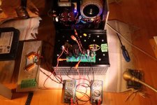
I tested the left channel board this morning. First with the Mosfet installed (no SIT) and dim bulb tester (DBT), passed. I then connected my 8R 100W test load in place of the SIT and powered up with DBT, and passed. Then it was powered up with no DBT. I monitored the current and SIT Vgs. With the trim pots set for minimum current and maximum Vgs, they measured 2.54A and -17.97V respectively.
So no shorts, current source was working properly, and plenty of Vgs available. Both the SIT Vgs and current were adjustable with the trim pots.
Now to connect the THF-51S.
So no shorts, current source was working properly, and plenty of Vgs available. Both the SIT Vgs and current were adjustable with the trim pots.
Now to connect the THF-51S.
Attachments
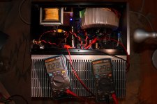
The left channel is powered up and cooking. No sparks or fireworks, so I have been slowly ramping up the current. It is nearly there at 2.93A. The goal is 3.0A. So voltages are good, but haven't checked with a signal. That will have to wait until tomorrow.
Picture with voltages was taken earlier:
Picture with voltages was taken earlier:
Attachments
Since this is just a pcb version of my earlier strip board version of the amplifier, I expect it to sound and measure the same. 🙂
people would argue: does wired amp sound better or PCB amp sound better? I would think PCB amp would sound better and be measured better.
Well, I would say that the strip board circuit is very similar to a printed circuit board. It is definitely not a bunch of loose wires.
The principal difference is the solder mask on the pcb, not necessarily a good thing.
Thinking of the neatness of a pcb versus point to point reminds me of the Futtermen H3aa amplifiers I had in the middle seventies - you would not believe what they looked like on the inside.
You have never seen such a jumble - parts that without doubt were bought on Canal Street junk shops - all in a web that looked like the spider had ingested cocaine along with too much coffee.
Julius and his brother in law would wind their power transformers. All of this sat atop a garden variety BUD box that was a bit overwhelmed by the load it had to carry. Even as mono amps without output transfomers they were lopsided heavy which made them awkward to carry.
Julius Futterman was a wonderful fellow. Always willing to talk to someone who was, if you can believe it, much dumber while in his twenties than today.
I never owned loudspeakers that were compatible with the amps - I just loved the way they looked with those plate caps on the output tubes. Of course, I would never have admitted that back then. Almost forgot the orange glowing voltage regulator tubes! As close as I will ever be to owning a lava lamp.
Futterman made his amps in his apartment on W. 72nd Street - not too far down the road from the infamous Dakota and its infamous residents. I would have rather spoken to Julius than any of them on any day.
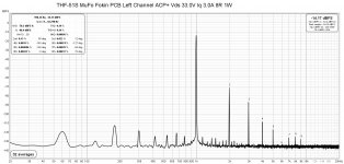
I did some measurements today. The 1W distortion @8R was measured. When compared to the measurement that I made over a year ago, the second harmonic is now higher. I don't know why. The operating point is the same. But then I am not using certified equipment in a certified lab so variations in test results can happen. I am not worrying about it since the results are in the same ballpark. There is slightly less noise now, but the previous noise level was already quite low and not audible through my 103dB speakers. Also I have found that the measured noise can be affected by all sorts of things, and can vary due to layout of equipment and cables. So all in all, I would say that the pcb design is a success.
I did want to investigate the frequency response since I reduced the capacitor at the input from 10uF to 4uF. LTSpice had said that it should not make a noticeable difference in the low end response but I wanted to verify that. I did a stepped frequency analysis with REW and it indicated a small drop-off 0f about 0.7dB at 20Hz. I didn't know whether that was correct or not so I manually did a check with a function generator inputting a signal and using a oscilloscope to monitor the input and output voltages at the amplifier. The measured voltages showed a reasonable flat frequency response from 20Hz to 40kHz:
THF-51S MuFo Fokin PCB Left Channel
Measured frequency response with HP3310A Function Generator and Rigol oscilloscope:
Freq.....Vrms In...Vrms Out
20Hz......3.03.......2.69
51Hz......3.05.......2.71
100Hz.....3.04.......2.73
140Hz.....3.04.......2.72
494Hz.....3.04.......2.72
1.0kHz....3.04.......2.71
3.0kHz....3.04.......2.66
5.1kHz....3.04.......2.64
9.8kHz....3.04.......2.65
13.1kHz...3.04.......2.68
20kHz.....3.04.......2.69
40kHz.....3.04.......2.66
So I am happy with the 4uF at the amplifier input.
While I had my oscilloscope out I checked my multimeter's 1kHz voltage measurement against the oscilloscope, and the meter was 3 percent low - close enough.
So the left channel pcb is good to go. Now to do the right channel.
Attachments

huge improvement over the strip board circuit version. it proves the theory, PCB is measured better.
waiting for your listening impression.
waiting for your listening impression.
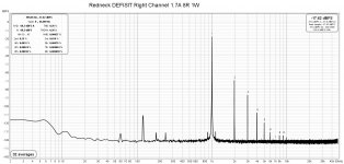
I wouldn't say the amp measured better just because of the pcb. I have seen many amps on diyAudio that incorporate pcbs that measured noisier than my strip board amp. I would say that my strip board version measured quite well. The main difference between the strip board and pc board version is that the pcb version has superior low level noise, with all other factors being equal. That may be due to the ground plane on the pcb. In both versions I tried to keep the loop areas small.
It is also possible to have a pcb perform worse than a strip board. It all depends on the design.
But other factors include keeping the loop areas from power supply to board small, and from speaker and signal input wiring to board small contributed to the measured performance.
But I am pleased with the pcb performance. Not bad for a amateur electronics diyer's first ever pcb design. 🙂
- Home
- Amplifiers
- Pass Labs
- Single Ended Tokin SIT THF-51S Common Drain Mu Follower Amplifier, 45W?