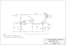
I am mostly curious how the pentode + choke load work, theoretically it shouldn't work (too low a load at LF), but the feedback can correct frequency response, at the expense of distortion?!
You were right to wonder about the choke load in the test circuit I used! While the choke load is just fine at low frequencies (LF behaviour can be tailored by adjusting the blocking capacitor) the choke hammers the HF response (-3dB@15kHz). I have reverted to an anode resistor, accepting a little more distortion in order to extend bandwidth above 20kHz (along with re-arranging other component values/voltages/currents to suit the resistive anode load on the EF184).
Hi bondini,
I think my post with the gyrator loaded pentode (post 30) got losts among the different comments, so I would like to point towards it again. Here are some experiments by @mogliaa with the gyrator loaded pentode. https://www.bartola.co.uk/valves/2013/01/12/4p1l-pentode-driver-test-2/
The text starts with some words from Gary Pimm, about the possibility of using CCS in parallel with resistors (just like @SpreadSpectrum did), but the necessity of tweaking for the desired plate voltage (necessary for a symmetric swing). When using the gyrator circuit one keeps the high load, but one avoids the need for tweaking, as the idle plate voltage will always be close to the voltage applied to the gate. This is so stable that I even use the source output from the gyrator loaded pentode (or triode) to bias the output tubes. With a gyrator loaded E180F I got gains over 1000x, nice for some NFB.
good luck with further experimentation!
Erik
Thanks, Erik - I may try loading the EF184 with a gyrator. Probably some time after I stop liking the sound of a simple 4K7 load resistor!
I would appreciate thoughts on extending the high frequency response the circuit on my bench. Presently, it is -3dB@21kHz, which is not ideal. To recap, replacing the 150H choke load with a 4K7 resistor as the anode load on the 6EJ7 extended the high frequency response. It is not improved/is unaffected by:
- altering the coupling cap at the output of the source follower;
- removing/inserting the source follower;
- changing the output transformer;
- changing the 6EJ7 topology to conventional pentode mode;
- applying a "compensation" capacitor in parallel with Rf1;
- increasing/decreasing the value of the 10uF coupling capacitor.
Attachments
The OPT? I would disconnect the feedback and measure FR at different points in the circuit, to check where it starts falling.
The OPT leakage reactance usually sets the upper limit of HF response.
Like attempting to push a rope up e hill. Doesn't matter what it is driven by. 🙂
Like attempting to push a rope up e hill. Doesn't matter what it is driven by. 🙂

Probably across Rf2, potentially with some series R, to reduce feedback where the roll off starts.applying a "compensation" capacitor in parallel with Rf1
Turns out that it was the inductive potentiometers in the test rig (I used them to adjust the amount of feedback) that were limiting the high frequency response. I replaced them with fixed value resistors and voila, bandwidth is now out to a respectable -3dB@37kHz on cheap output transformers.
In which position?inductive potentiometers
Edit: just saw it's Rf1. Wouldn't inductance - and it would need a lot - decrease feedback at high frequencies and cause a rise in response?
Last edited:
Wirewound potentiometers at Rf1 and Rf2, measuring 2.2mH and 57mH respectively, no measurable capacitance (without going the whole hog and setting up the bridge).
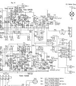
Just like the RH84 design, it uses plate-to-plate feedback, this time from the ultra-linear tap on the primary. You may find out more posting the design on an RH84 thread than on this plate-to-cathode feedback thread.
"You may find out more posting the design on an RH84 thread than on this plate-to-cathode feedback thread."
Sorry, maybe an administrator can delete the post or move it to a more appropriate thread?
Sorry, maybe an administrator can delete the post or move it to a more appropriate thread?
- Home
- Amplifiers
- Tubes / Valves
- Single ended pentode with plate-to-cathode feedback