The picture on article of Schade is different and on it I am playingNot really Walter
And the consideration about % would be the same for Bartola and also dependance on tube type
Unfortunately I am servicing my Sofia that has an issue so I can’t play with it
What I see they aren’t test in deep around Schade config but the first impression aren’t good
I will go ahead
Walter
That's why I suggested you to study and investigate more based on the evolution of the concept, suggesting different circuits and tests of other people, not just the original paper. It's not only a matter of the tube itself, but also the right driver to chose for this kind of feedback.The picture on article of Schade is different and on it I am playing
This forum (and all the related links outside the forum) is full of information of people who measured the curves of a moltitude of tubes applying different local feedbacks.
Each pair of valve and configuration give a specific result, and a specific limit for the amount of Schade feedback after which the increase is detrimental for the overall amp. To understand these points you need to read tests and considerations by other experienced people and understand strong and weak points about different configurations.
If your first impression is not good, it means you are not doing things right.

There are the first test I post here and they say somethingIf your first impression is not good, it means you are not doing things right.
And look around I never seen the same pattern of test with real circuit and not simulation
The way I follow is right
And other test wil be done
I have four different OT to play with different config so at the end some consideration will come
Walter
The link I posted in the previous page is a curve tracer showing results on a real tube. It's plenty of similar information on this forum.
Others have shown results of complete circuits decades ago on this forum and linked other tests outside the forum.
Some data has been lost over the years (a russian forum with tests varying Vg2 and Vg3 is no more available), but most of it is still available.
You just need to find them without reinventing the weel.
It seems that with sand and simulation other try to reinvent a Square wheelYou just need to find them without reinventing the weel.
But , I repeat, at the end of the play something will come out
Walter
Once more I try to help you and you are only able to attack and denigrate with no understanding.
My contribution stops here. You deserve nothing.
My contribution stops here. You deserve nothing.
You can’t help me just only because I haven’t seen any real test lab of your stuff made around this configOnce more I try to help
And I can continue with my research
Walter
Sorry for the intrusion again, I wasn't talking about curves, but about transient response which with that connection to the Shade translates the transient response from pentode to triode. If I can I'll show you some measurements.The curves in Schade are similar to UL config. and not triode,
The picture in the original article show the curves
Walter
OkIf I can I'll show you some measurements.
Even I can’t understand the “transient response” related to the triode or pentodo config
Walter
HiThese below are Schade feedback curves obtained by a curve tracer 12 years ago:

Reference: https://www.bartola.co.uk/valves/2013/03/16/307a-dht-in-triode-and-schade-feedback/
Can someone draw the schematic and explain with formula Shade concept?
How to calculate amount of Feedback? what is the elements configuration etc.
Please?
.
Is feedback amount, ratio of R2 / R1 in this schematic?
The artcleCan someone draw the schematic and explain with formula Shade concept?
https://www.dos4ever.com/uTracer3/Schade.pdf
I am playing with different config of FB
Walter
all'onda quadraOk
Even I can’t understand the “transient response” related to the triode or pentodo config
Walter
THANKSThe artcle
https://www.dos4ever.com/uTracer3/Schade.pdf
I am playing with different config of FB
Walter
Now it is a significantly more clear.
feedback amount for n less than 1 where 1 is 100%
n = R1 / ( R1 + R2)
I will redraw the schematic to more clear variations.
there is some mismatch on the schematic 50uF/35V should be marked as C2
last line in the picture...
.
.
btw
on Bartola Schematic R1=10K Rpot should be set to 90K for n=0.1 10%
"G" point is not for the input signal as from the way of drawing could be conluded, BUT for negative grid bias.
This is for measurement only - that was confusing...
.
For operational circuit, we need couling C in between R1 and R2 at the very G1 pin3.
With R1=10K, it is actually Rg, that coupling C should be minimum 10uF.
Note that in original Shade sch transformer used - not coupling C, so the 10K value is more appropriate.
.
Last edited:
In my case is around 13%. But is a first stepBartola Schematic R1=10K Rpot should be set to 90K for n=0.1 10%
Walter
?In my case is around 13%. But is a first step
Please show calculations of FB % in Your arrangement?
.
The closest I can get is 15%
R1 = (39K II 39K )=19.5K, R2=10K+100K=110K
n=19.5K / (19.5K + 110K)=0.15
.
or I am calculating wrong way?
I have took the signal on load. We have to consider also some lossor I am calculating wrong way?
On firsts test poster there is a value. More than 13 dB
I every case I will change a little bit the config with a pot to check different ratio of FB
The schematico is the one I will use; until now I used only the power stage
Walter
Next step will the use of a pot to set different % of FB having as 0 dB as level in pentode config
Checking the freq.response, the variatin of level moving from 8 to 4 ohms and FFT, in case also phase
Checking the freq.response, the variatin of level moving from 8 to 4 ohms and FFT, in case also phase
I also built a balanced PP pentode amplifier without general feedback, but connected to Shade which behaves like a PP triode, but with pentode power. I basically connected only 2 resistors...
Attachments
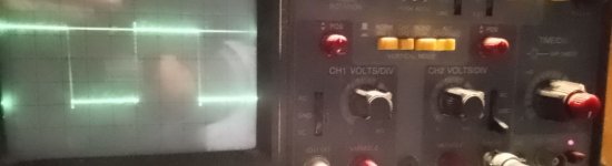
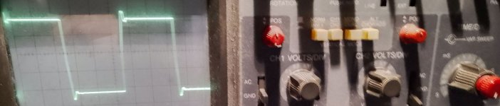

I have seen the pictureall'onda quadra
It seems be good but I mean a set of test more in deep
Walter
- Home
- Amplifiers
- Tubes / Valves
- Single Ended Double Tap Ultralinear Transformer + Schade config. tests