This am I listened to the Bottlehead Mainline, their TOTL headphone amp for the masses.
With my session with their Crack with Speedball the T2 IMO was a nicer overall presentation.
But with the Mainline the T2 comes close but the Mainline is still a nicer amp than the T2 IMO. The soundstage is similar to the T2 but the Mainline is even more wider, open and clear.
Now to be fair we are compairing a less than $200 amp to a $1299 kit amp. Bottlehead has really done a nive job with their amp...
...as well as Mark has done with the T2.
Still an awesome amp ...
Alex
It's all good, there's plenty of room in the playpen for everybody.
I expect that a thermal imaging camera picture of the Bottlehead Mainline, would show higher temperatures than anything on T2 (photo 1 of post #1 in this thread) 🙂
I expect that a thermal imaging camera picture of the Bottlehead Mainline, would show higher temperatures than anything on T2 (photo 1 of post #1 in this thread) 🙂
Good old 6L6 razzed me a bit about the schematics for T2, correctly observing that the two-level hierarchy and the large number of connect-by-name signals I used, would be confusing to many folks. Since brand new DIYers will likely be attracted to the (relative) simplicity of T2 and its (relatively) low cost, he convinced me to change the schematics & make them a lot more beginner friendly.
Thus I redrew the T2 schematics using the LTSPICE graphics editor; they are now the top two embedded images in post #2, at the beginning of this thread. There is one schematic for the audio signal path, from input RCA to output headphone jack and preamp output RCA. And there is a second schematic for the on-PCB power supply circuits.
I used LTSPICE's presupplied schematic symbol of an enhancement mode, Nchannel MOSFET, and then I also added the comment text "(Nch)" to eliminate any trace of ambiguity. I had to draw a few symbols myself, for components that LTSPICE does not supply, and so the blame for any inelegances you may see, falls to me alone.
To the best of my knowledge these schematics exactly match the layout and silkscreen markings on the PCB. But remember that To Err Is Human if you happen to find one or more mistakes.
These are large, high-res graphical images (.png); click on the white X at lower left to make them display at full size, then download the fullsize image to your computer for convenient viewing later when you don't happen to be logged-in to diyAudio.
_
Last edited:
I just changed the power on LED from yellow to green...
What a difference in the sound!!!!
😱😀🙂
Alex
What a difference in the sound!!!!
😱😀🙂
Alex
Mark as I sit here this am amd listen via the T2 with HD600's....I put my hand on the top case and its ever slightly warm.
So I was asking myself this question after owning other CLASS A amps....why are some of these other CLASS A amps so "hot" compared to your design?
I will not mention names but some head amps use the case as a heatsink...and they get hot to the touch. I know the heat has to go somewhere....and maybe its not an issue but the past 2 Class A amps have run really slightly warm to the touch.
One of these other amps has an internal power transformer while the others have external walwarts?
Any comments...
Alex
I can't speak for other designers and I certainly don't know why they chose to build a headphone amp that consumes X watts or whose case external temperature is Y degrees Celsius.
I do know that T2's thermal characteristics are not the least bit secret or mysterious. (i) its Galaxy 1U chassis has vents in the top and bottom panels; (ii) T2's PCB includes ventilation holes near the high power components; (iii) all four transistors are mounted on heatsinks; (iv) the power resistor is implemented as a series-parallel combination of four individual resistors, each rated for 3W; (v) the output transistor's datasheet max power rating is 20X greater than the power it actually dissipates in the T2 circuit; (vi) the rubber "feet" in the T2 BOM are 13mm tall, lifting it up above the tabletop to allow better airflow. Standard textbook stuff, utterly conventional.
Circuit analysis will tell you the exact amount of supply current drawn by the amplifier; it's less than 200 milliamps per channel. Then arithmetic gives the total power dissipation. With a 24V wall wart, total power must be less than 9.6 watts. Pump 9.6 watts into a Galaxy 1U chassis, how hot does it get? That's how hot T2 gets.
PCB arrived last week, thanks Mark.
Looking forward to getting this assembled in the near future.
Looking forward to getting this assembled in the near future.
Improvements to T2 and to its documentation
I just received a very nice PM from a diyAudio member who built a T2, and sent me a dropbox link to several photos, build notes, and listening notes. I hope he decides to share those with the entire diyAudio community!
His build notes offered a suggestion which I think deserves to be mentioned right away.
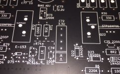
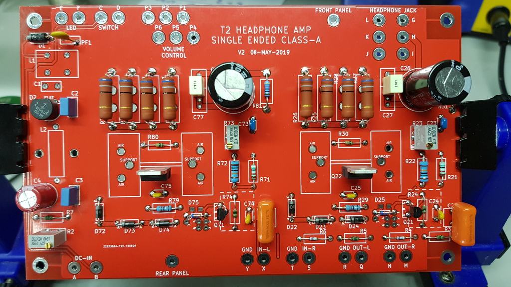
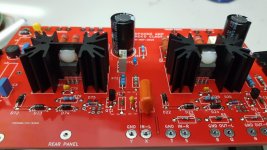
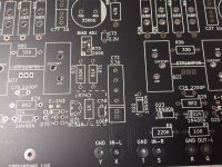
Well, as it turns out, I had made a cosmetic revision to the T2 PCB last week, which happens to have addressed this suggestion. The revision writes the component value next to the component ID (for example: C1 0.33U) on the PCB silkscreen. It also increases the footprint size of the input capacitors, allowing DIY experimentation with larger capacitors, fancy dielectrics, expensive brands, multiple caps in parallel, etc. Have a look at the picture below.
In the center of the photo is the footprint for C72. It's a tall narrow rectangle, and it's marked "C72 3.3U". A pair of horizontal lines separate the cap-pin-1 drill holes (bottom) from the cap-pin-2 drill holes (top). To make it clear which drill holes are shorted together and which are not, I placed a square pad around the cap-pin-1 holes,and a round pad around the cap-pin-2 holes.
I plan to build up a T2 on this new board and, if everything works as it should, put it in the diyAudio Store. I'll probably wind up with some excess boards, which I will again sell at my cost. These might be an interim source of supply, while the Store performs all of its necessary logistics to add a new product.
_
I just received a very nice PM from a diyAudio member who built a T2, and sent me a dropbox link to several photos, build notes, and listening notes. I hope he decides to share those with the entire diyAudio community!
His build notes offered a suggestion which I think deserves to be mentioned right away.
The 3.3uF input capacitors (C22, C72) are poorly marked on the PCB silkscreen. It's not clear which cap is C72, and it's also not clear how to stuff the leads (which pins go in which holes?)
Well, as it turns out, I had made a cosmetic revision to the T2 PCB last week, which happens to have addressed this suggestion. The revision writes the component value next to the component ID (for example: C1 0.33U) on the PCB silkscreen. It also increases the footprint size of the input capacitors, allowing DIY experimentation with larger capacitors, fancy dielectrics, expensive brands, multiple caps in parallel, etc. Have a look at the picture below.
In the center of the photo is the footprint for C72. It's a tall narrow rectangle, and it's marked "C72 3.3U". A pair of horizontal lines separate the cap-pin-1 drill holes (bottom) from the cap-pin-2 drill holes (top). To make it clear which drill holes are shorted together and which are not, I placed a square pad around the cap-pin-1 holes,and a round pad around the cap-pin-2 holes.
I plan to build up a T2 on this new board and, if everything works as it should, put it in the diyAudio Store. I'll probably wind up with some excess boards, which I will again sell at my cost. These might be an interim source of supply, while the Store performs all of its necessary logistics to add a new product.
_
Attachments
T2 Review and Construction Notes – Part 1 of 2
First, congratulations are owed to Mark for an excellent sounding headphone amplifier design. It exhibits smooth, detailed, extended frequency response and is dead quiet. It is well behaved with no turn on transient and a very minor and acceptable turn off thump. Imaging and sound stage width is very good. Good damping across the entire frequency range results in a taming of headphone transducer high frequency harshness and yields tight bass response. This does not result in coloration or loss of detail.
Overall, the presentation is neutral and balanced. This would be an excellent reference amplifier for studio monitoring applications. The only drawback I found is the low gain, which limits its use with low sensitivity headphones.
My main comparison was made to a Pete Millett NuHybrid headphone amplifier, featuring the low voltage Korg NuTube dual triode device. It features BJT input buffers and high current opamp outputs. My specific build is modified with Jensen JT-11P-1 input transformers with reversed primaries to correct the polarity inversion inherent in that triode circuit. Plate resistors were changed from 475K to 332K and plate voltage was reduced from 11.5 to 9.7 to match the Nelson Pass recommendations for the Korg tube. I have another amp, the old AX GP40 design, which is a chip amp circuit run in quasi-class A mode as well as a CMOY battery powered opamp circuit but I don't consider either of those in the T2 league so I did not do a comparison with them.
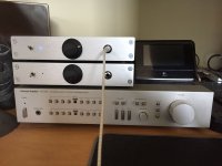
Both the T2 and the Millett were built with an Alps RK27 series 10K audio taper stereo potentiometer at the front end. Both were built into diyAudio store Galaxy chassis and use the same Mean Well 1.04A 24VDC power supply. The T2 uses a custom front panel and the supplied rear panel.
Headphones used in the listening evaluation were:
Sennheiser HD 380 Pro closed back dynamic, 62 ohms, 102 dB/mW sensitivity
Sennheiser HD 555 open back dynamic, 100 ohms, 103 dB/mW sensitivity
Master & Dynamic MH40 closed back dynamic, 34 ohms, 105 dB/mW sensitivity
HiFiMan 400i open back planar magnetic, 42 ohms, 93 dB/mW sensitivity
The HiFiMan 400i were the only phones that could not be driven to full volume by the T2. The NuHybrid had gain to spare with all transducers.
Music selections included a mix of studio and live recordings that included male and female vocals, trio and orchestral jazz and popular music. The T2 is very easy to listen to, even on the more difficult Sennheiser cans, which tend to sound a bit harsh and veiled with typical amplifiers. None of that here. In fact, the T2's “lifting of the veil” on the Sennheisers is almost magic and is now pushing me to consider buying a pair of HD 650s to use with this amp.
That said, the NuHybrid is the more exciting amplifier. It gets my toe tapping. The music is more dynamic and the sound stage wider. The 1.5% second order harmonic distortion from the triode does have its own magic. The amp also effortlessly drives the planar magnetic cans, albeit with a slightly higher noise floor and a nasty turn off pop that pretty much requires disconnecting the headphones before power down.
Conclusion: both amplifiers hold their own in the audiophile arena when matched with headphones under $1000. I can't see getting rid of either of them, as they are both excellent and each provides a very different listening experience.
First, congratulations are owed to Mark for an excellent sounding headphone amplifier design. It exhibits smooth, detailed, extended frequency response and is dead quiet. It is well behaved with no turn on transient and a very minor and acceptable turn off thump. Imaging and sound stage width is very good. Good damping across the entire frequency range results in a taming of headphone transducer high frequency harshness and yields tight bass response. This does not result in coloration or loss of detail.
Overall, the presentation is neutral and balanced. This would be an excellent reference amplifier for studio monitoring applications. The only drawback I found is the low gain, which limits its use with low sensitivity headphones.
My main comparison was made to a Pete Millett NuHybrid headphone amplifier, featuring the low voltage Korg NuTube dual triode device. It features BJT input buffers and high current opamp outputs. My specific build is modified with Jensen JT-11P-1 input transformers with reversed primaries to correct the polarity inversion inherent in that triode circuit. Plate resistors were changed from 475K to 332K and plate voltage was reduced from 11.5 to 9.7 to match the Nelson Pass recommendations for the Korg tube. I have another amp, the old AX GP40 design, which is a chip amp circuit run in quasi-class A mode as well as a CMOY battery powered opamp circuit but I don't consider either of those in the T2 league so I did not do a comparison with them.
Both the T2 and the Millett were built with an Alps RK27 series 10K audio taper stereo potentiometer at the front end. Both were built into diyAudio store Galaxy chassis and use the same Mean Well 1.04A 24VDC power supply. The T2 uses a custom front panel and the supplied rear panel.
Headphones used in the listening evaluation were:
Sennheiser HD 380 Pro closed back dynamic, 62 ohms, 102 dB/mW sensitivity
Sennheiser HD 555 open back dynamic, 100 ohms, 103 dB/mW sensitivity
Master & Dynamic MH40 closed back dynamic, 34 ohms, 105 dB/mW sensitivity
HiFiMan 400i open back planar magnetic, 42 ohms, 93 dB/mW sensitivity
The HiFiMan 400i were the only phones that could not be driven to full volume by the T2. The NuHybrid had gain to spare with all transducers.
Music selections included a mix of studio and live recordings that included male and female vocals, trio and orchestral jazz and popular music. The T2 is very easy to listen to, even on the more difficult Sennheiser cans, which tend to sound a bit harsh and veiled with typical amplifiers. None of that here. In fact, the T2's “lifting of the veil” on the Sennheisers is almost magic and is now pushing me to consider buying a pair of HD 650s to use with this amp.
That said, the NuHybrid is the more exciting amplifier. It gets my toe tapping. The music is more dynamic and the sound stage wider. The 1.5% second order harmonic distortion from the triode does have its own magic. The amp also effortlessly drives the planar magnetic cans, albeit with a slightly higher noise floor and a nasty turn off pop that pretty much requires disconnecting the headphones before power down.
Conclusion: both amplifiers hold their own in the audiophile arena when matched with headphones under $1000. I can't see getting rid of either of them, as they are both excellent and each provides a very different listening experience.
Attachments

T2 Review and Construction Notes - Part 2 of 2
I really liked the PCB design with one very minor exception. The silkscreen at output bypass cap locations C27 and C77 is confusing at first glance. It looks like the cap should go inside the bottom rectangle instead of bridging the two rectangles. It does not help that the specified cap fits right into that lower rectangle, effectively taking it out of the circuit (no harm done except theoretically some loss of high frequency response).
As far as the front and rear panels, I would like to suggest an alternative to using a ring lug under one of the mounting screws, which raises just that one corner off of flat. Exposing a patch of ground plane on the inside of the front or rear panel with some careful sanding makes it easy to surface tack a wire to that point and run it to the PCB ground point. Maybe a future board release could add the grounding patch option?
Galaxy front and rear panels come with flat head screws which don't work well with the PCB panels. Actually I used some old rack screw plastic washers on the rear and was able to skate on buying new screws since the front panel was the original galaxy with a bit of drill press work.
I've been buying Alps volume pot adapter boards on eBay and really like them. A PCB that accommodates RK27, RK16 and RK09 pots is just 99 cents and SpeedPak shipping from China is just $1.80 regardless of quantity (within reason). I bought 10, which is probably a lifetime supply. You just have to wait a few weeks for shipping.
Adapter PCB for ALPS RK27 RK16 RK09 Potentiometer Volume Pot PCB conection Board 699945764230 | eBay
I did not buy or use an LED trim pot since I already knew the LED and resistor I wanted to use. I use a 1/16” hole in the front panel with a small block of wood drilled and foam taped to the back side as an adapter for a standard 5mm blue LED. My volume knob is an “old school” Raytheon military style knob made by ECH (available from Newark Electronics).
https://www.newark.com/ehc-electron...f2b/round-skirted-knob-w-arrow-ind/dp/88F4383
PCB stand offs are brass with bottom panel paint under them ground off and the steel coated with a little DeOxit Red (actually, I still have a little Cramolyn Red left over from the early 1980's, but that's showing my age). I recommend the DeOxit wherever you have bare metal contact especially if the metals are dissimilar. Also keep in mind that anodized aluminum does not conduct, even clear anodizing. Sometimes aluminum is clear alodined, which is conductive. When in doubt, check with a meter.
One more trick with the Galaxy chassis is a couple of very small strips of duct tape stacked under each top and bottom panel nut since the screws are too short to grab the nut threads easily. Just stick the nut to the tape and slide it into the channel.
Thanks very much for posting your build and your listening impressions. You may be the only person on earth with a pair of exactly matching headphone amplifiers, one of them a diyAudio T2 and the other a Millett NuHybrid HPA.
Thanks very much for posting your build and your listening impressions. You may be the only person on earth with a pair of exactly matching headphone amplifiers, one of them a diyAudio T2 and the other a Millett NuHybrid HPA.
Actually, you can't see it in the photo but the Millett is in a 230 X 230 Galaxy and yours is in a 230 X 170.
Even though the Millett has a smaller PCB, I wanted room for the Jensen JT11-P-1 input transformers I'm using to correct the signal polarity inverted by the triode device. That's not a problem with your T2 design.
Beautiful craftsmanship on both builds.
It might be really interesting to figure out a way to change from noninverting to inverting and vice versa, instantly, at the touch of a button. Maybe a couple of DPDT relays which swapped the hot and cold output windings of the Jensen transformers, might be one way to do it.
It might be really interesting to figure out a way to change from noninverting to inverting and vice versa, instantly, at the touch of a button. Maybe a couple of DPDT relays which swapped the hot and cold output windings of the Jensen transformers, might be one way to do it.
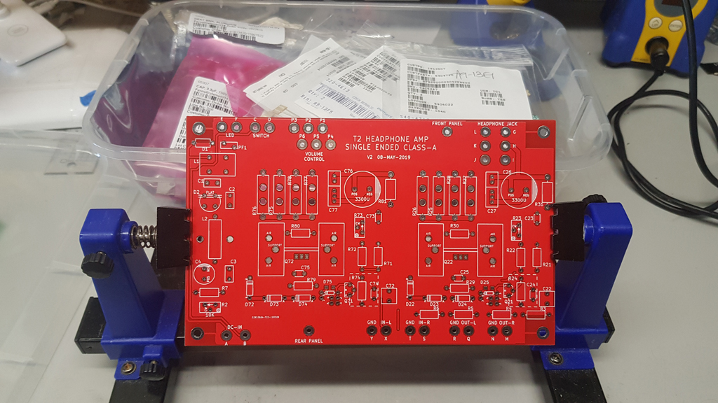
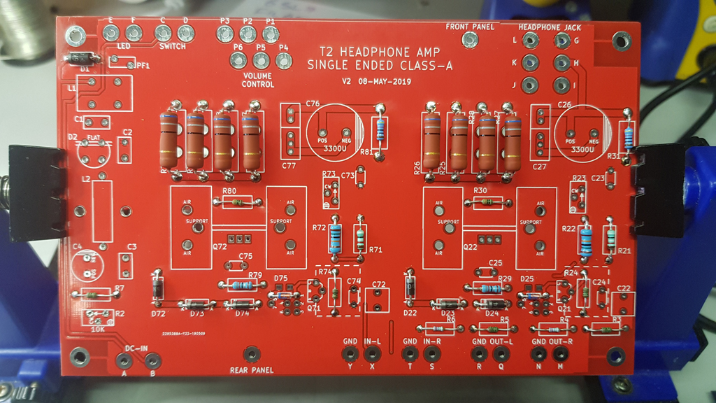
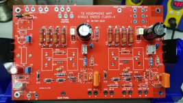
Thanks for the design of this HPA. I've completed mine apart from the chassis (awaiting shipment still). I hope you don't mind me sharing some photos here.
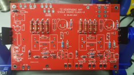
Fresh board ready to go:
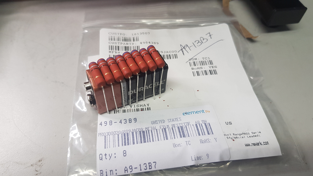
I found the perfect template for the power resistors:
Resistors and Diodes in:
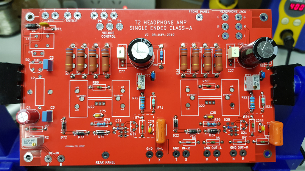
Installed the caps:
Heatsinks temporarily installed with plastic clips:
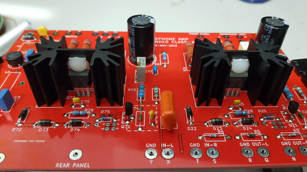
Transistors next:
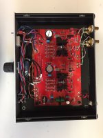
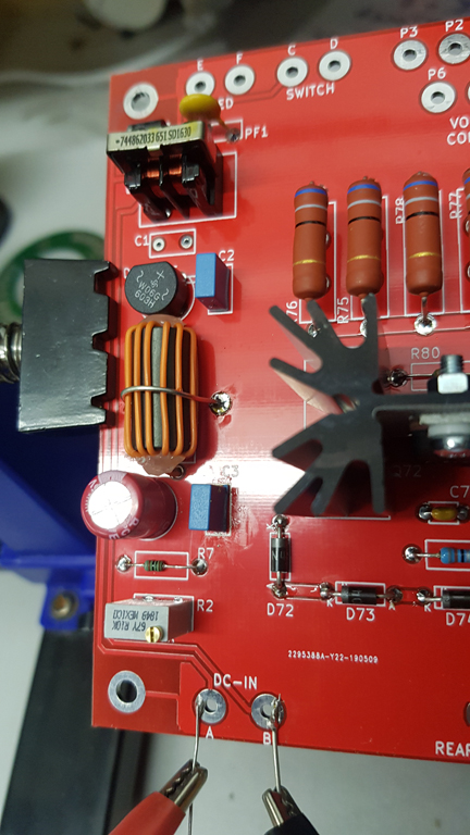
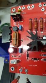
Choke and inductor:

Found out the hard way that the Cat-5 wire I used for the inductor was made of Aluminium (wouldn't solder). Start again!

Close up of the inductor. I used Tinned Wire as strapping. Not sure if there will be any kind of magnetic coupling to worry about, but I think it looks nicer 😉
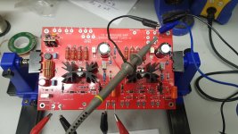
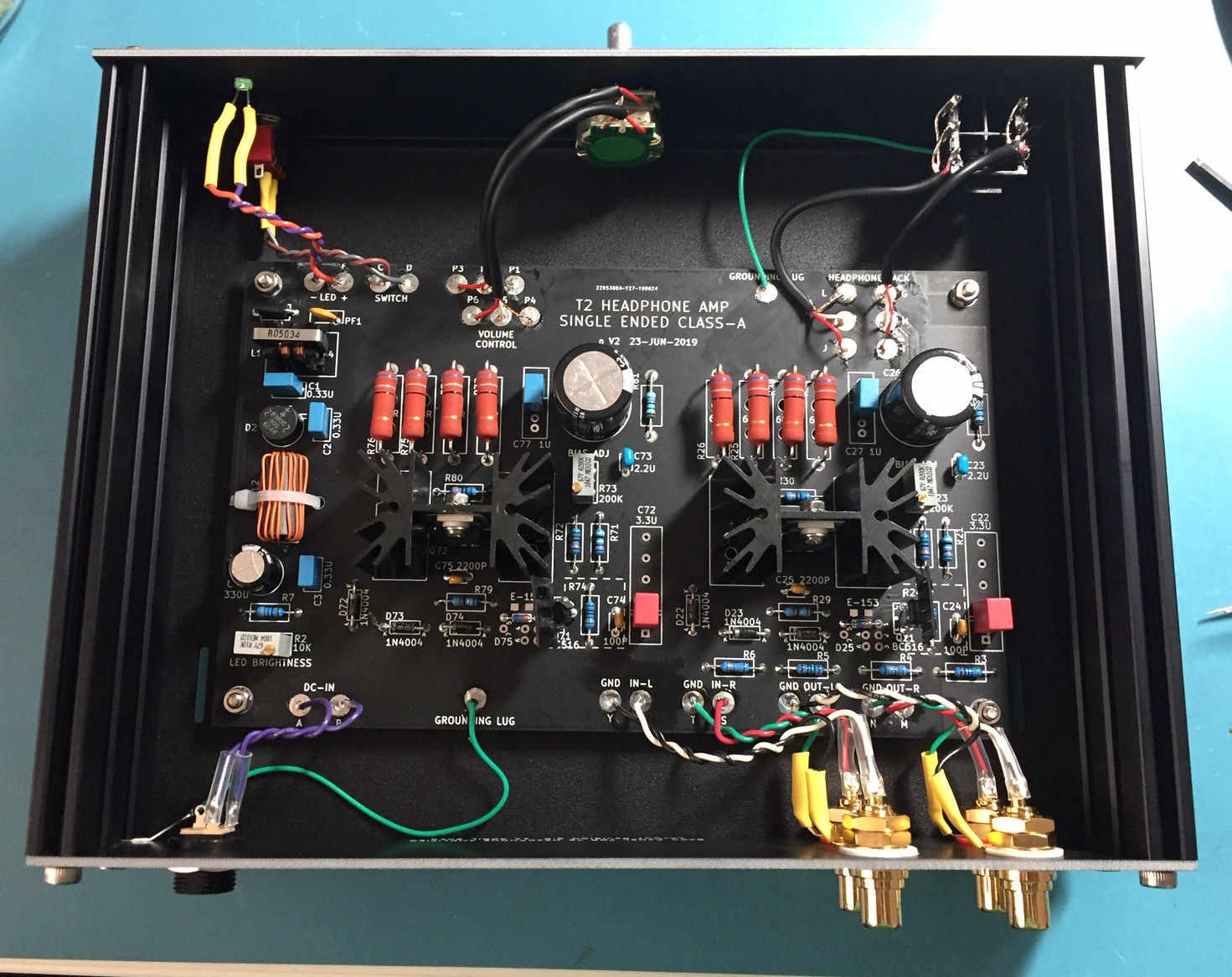
And ready to test!

Fresh board ready to go:
I found the perfect template for the power resistors:
Resistors and Diodes in:
Installed the caps:
Heatsinks temporarily installed with plastic clips:
Transistors next:
Choke and inductor:
Found out the hard way that the Cat-5 wire I used for the inductor was made of Aluminium (wouldn't solder). Start again!
Close up of the inductor. I used Tinned Wire as strapping. Not sure if there will be any kind of magnetic coupling to worry about, but I think it looks nicer 😉
And ready to test!
Attachments
-
 20190702_192808.jpg283.2 KB · Views: 759
 -
 20190702_192150.jpg494.2 KB · Views: 755
 -
 20190702_185745.jpg577.1 KB · Views: 757
 -
 20190702_163106.jpg609.5 KB · Views: 763
 -
 20190702_153044.jpg604.9 KB · Views: 762
 -
 20190702_152555.jpg448.9 KB · Views: 757
 -
 20190702_151634.jpg592.8 KB · Views: 749
 -
 20190702_123307.jpg557.2 KB · Views: 751
 -
 20190702_115719.jpg333.6 KB · Views: 744
 -
 20190702_112904.jpg473.5 KB · Views: 748
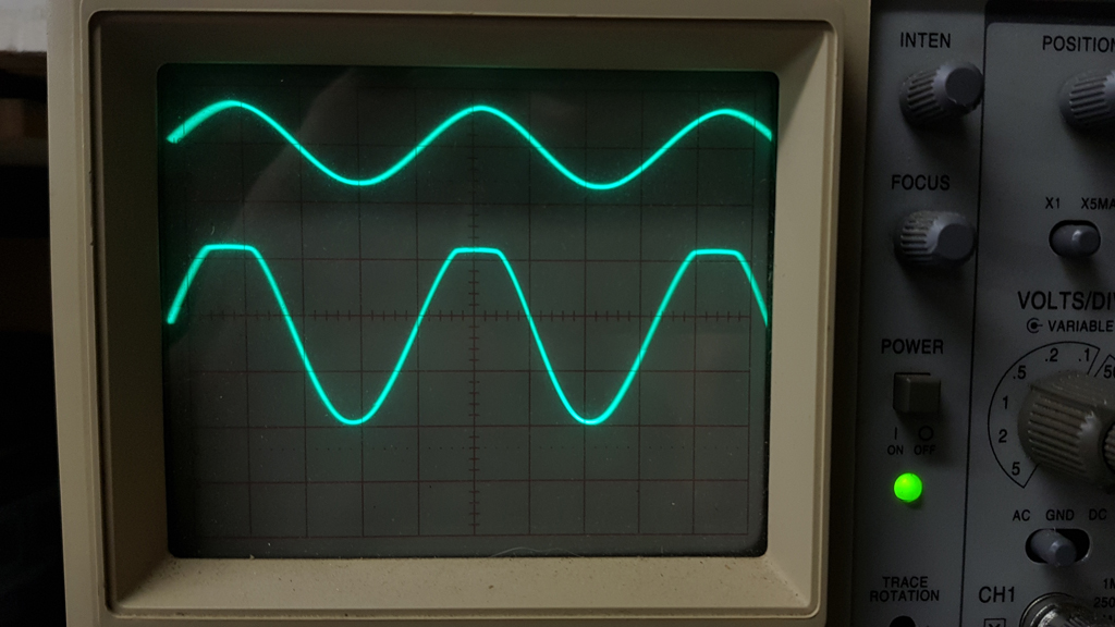
1KHz Sine wave:
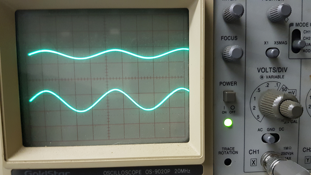
Excellent 1KHz Square wave response:
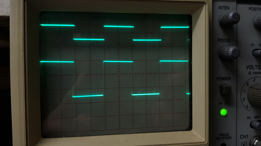
Clipping, top half goes first.
*******************
I've connected up the amp to a pair of sacrificial headphones and the amp is dead silent at idle - even outside of a faraday cage.
It sounds great so far, but I'm waiting for the chassis and plug in decent headphones before I make any judgement (but sounds good so far!!).
Thanks again Mark!
Excellent 1KHz Square wave response:
Clipping, top half goes first.
*******************
I've connected up the amp to a pair of sacrificial headphones and the amp is dead silent at idle - even outside of a faraday cage.
It sounds great so far, but I'm waiting for the chassis and plug in decent headphones before I make any judgement (but sounds good so far!!).
Thanks again Mark!
Attachments


Very nice, avtech23! It is not surprising that the 1 kHz square wave looks good since the 200 kHz square wave (post #2 attachment 6) also looked good. As for the asymmetric clipping: perhaps it is a fun exercise to figure out WHY the top clips before the bottom. There's only two amplification "stages" at one transistor per stage, it can't be all that complicated, can it?
As mentioned in post #150, I made a very slight revision to the T2 PCB before putting it into the diyAudio Store. The changes were minor
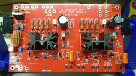
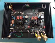
I got the boards back from the Chinese PCB fab and built a T2 headphone amp using the new board set, just to verify that the boards are still okay. It worked as expected and this is the final PCB "spin" that I'm going to work with diyAudio Supreme Commander Jason, to get into the Store. A few photos are below.
I do have some extra boards left over from this experiment, which I am willing to sell at my cost while we wait for them to appear in the Store. They are black, not red, see photos below.
If anybody wants to build a T2 right away and does not wish to wait for the Store, I'll let you have a set of three PCBs (front and rear panel + black main amplifier board) for $16.50 if shipped inside USA, or for $26.50 to the rest of the world. Send PM for PayPal info.
Mark Johnson
edit- yes the volume control is a little different. I've installed a "DACT" 28-position stepped attenuator that I bought on eBay, instead of the ALPS Blue Velvet potentiometer seen in posts #1-#4. It's an experiment! Woo hoo, I DIYed something!
_
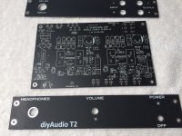
- Modify front panel lettering to use the same typeface font as the back panel: see photos
- Put each component's value (in ohms, farads, etc) on the PCB silkscreen layer next to the component ID: see photos
- Enlarge the PCB footprint of the input capacitor C22 & C72, allowing more room for DIY experimentation with expensive or exotic capacitors: see photos
I got the boards back from the Chinese PCB fab and built a T2 headphone amp using the new board set, just to verify that the boards are still okay. It worked as expected and this is the final PCB "spin" that I'm going to work with diyAudio Supreme Commander Jason, to get into the Store. A few photos are below.
I do have some extra boards left over from this experiment, which I am willing to sell at my cost while we wait for them to appear in the Store. They are black, not red, see photos below.
If anybody wants to build a T2 right away and does not wish to wait for the Store, I'll let you have a set of three PCBs (front and rear panel + black main amplifier board) for $16.50 if shipped inside USA, or for $26.50 to the rest of the world. Send PM for PayPal info.
Mark Johnson
edit- yes the volume control is a little different. I've installed a "DACT" 28-position stepped attenuator that I bought on eBay, instead of the ALPS Blue Velvet potentiometer seen in posts #1-#4. It's an experiment! Woo hoo, I DIYed something!
_
Attachments
Last edited by a moderator:
- Status
- Not open for further replies.
- Home
- Amplifiers
- Headphone Systems
- Single ended class-A headphone amp using two transistors: T2