beppe61 said:So I would need a confirmation on the following:
Do I have to put a voltage divider in front of Q1 to get 7V at the Q1 base
and of course a nice input coupling cap ?
Yes, two resistors voltage divider.
These two resistors will also set Input Impedance
and so also size of Input Capacitor.
lower Input resistors = lower input impedance = bigger cap
higher values resistors = higher input impedance = lower value cap
I would suggest
Resistor from 7.0 Volt to ground be in span: 47 kOhm - 100 kOhm.
The other upper Resistor have related value to make 7 Volt.
To find this value, you can use a 1 MOhm trim potentiometer.
After you replace with same value Resistor.
Input capacitor can be: 1uF - 2.2uF
if lower Resistor is 47 kOhm -100 kOhm
Originally posted by lineup
1) Yes, two resistors voltage divider.
These two resistors will also set Input Impedance
and so also size of Input Capacitor.
lower Input resistors = lower input impedance = bigger cap
higher values resistors = higher input impedance = lower value cap
I would suggest Resistor from 7.0 Volt to ground be in span: 47 kOhm - 100 kOhm.
The other upper Resistor have related value to make 7 Volt.
2) To find this value, you can use a 1 MOhm trim potentiometer.
After you replace with same value Resistor.
3) Input capacitor can be: 1uF - 2.2uF
if lower Resistor is 47 kOhm -100 kOhm
Thank you Mr. Lineup for the explanation.
1) Very interesying the fact about the input impedance.
If it is high I can use low uF high quality input cap.
2) Is it not possible to calculate it instead of using the trimmer?
It should be easier.
3) I have already some nice PP caps to try. Thanks.
Besides, have you seen the sim results?
Quite astonishing eh ?
I thought never possible to get this kind of distortion spectrum from such a basic topology.
This reinforces my interest on simpler topologies.
I am very curious to try this schema and listen.
Regards,
beppe
beppe61 said:1) Very interesting the fact about the input impedance.
If it is high I can use low uF high quality input cap.
2) Is it not possible to calculate it instead of using the trimmer?
It should be easier.
3) I have already some nice PP caps to try.
Thanks.
Thanks Sir beppe61 for your always kind words.
1. Formula to see what capacitor you need:
f = frequency in Hertz where frequency curve is down -3dB.
Tones < f Hz can not be heard so well.
f should be something like 5-20 Hertz
C = capacitance, Farad.
R = impedance, Ohm.
f = 1 / ( 2pi x R x C )
-------------------------------------------
example: R = 30kOhm, C = 1uF
f = 1 / ( 2 x 3.14 x 30000 x 0.000001 )
f = 1 / 0.1884
f = 5.307 Hertz
Amplifier lower freq limit will be ~ 5.3 Hertz
470nF and 1uF Polypropylene caps are good to have home.
1uF will do good for input impedance 22kOhm->100kOhm
That is for most amplifiers.
-----------------
2. Yes, you can calculate. and get almost 7.0 Volt.
Use R1 = 47 kOhm for lower resistor, 7.0 input - GND.
+V supply is 24 VDC
I = U/R , Ampere = Volt/Ohm
Current in resistor R1 = 7 Volt / 47000 Ohm = 0.000149 Ampere
Volt across upper resistor: 24-7 = 17 Volt
Same current in R2 (almost same, a little current goes into T1 Base)
R = U/I , Ohm = Volt/Ampere
R2 = 17 Volt / 0.000149 Ampere
Upper resistor, R2 = 114093 Ohm, 115kOhm (= 100k+15k two resistors)
Input impedance will be, R1 in parallel with R2,
47k//115k, will make a resistance of:
1 / [ (1/R1) + (1/R2) ]
1 / [ 0.0000212 + 0.0000086 ] = 33557 Ohm
Input impedance will be like 33kOhm.
lineup said:Thanks Sir beppe61 for your always kind words.
1. Formula to see what capacitor you need:
...
Input impedance will be like 33kOhm.
Dear Mr. Lineup,
thank you.
Know I have all the data necessary to the construction.
As soon as I will have some practical results I will post here my findings.
Thank you for your kind support.
Kind regards,
beppe
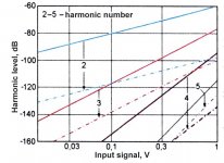
Thanks to X-Pro for good explanations!
Attached is a measured harmonics level improvement shown by arrow for each harmonic number.
Measured for russian KT3102 transistors with 3.5 V over R2 on the x-pro post #27 schema.
Simulation and measurement well coincide, THD for KT3102 drop from 0.11% to 0.0017% for 1 V input. With other transistors more or less may be but by the factor of two order.
A circuit output OUT2 not only voltage but also current corrected if apply low impedance between OUT2(post #27) and positive rail or ground.
An error correction in circuit due to R3 (post #27) add a compensation of Q2_Ube variation to the output in proper value and phase.
Attachments
Mikhail__K said:Thanks to X-Pro for good explanations!
Attached is a measured harmonics level improvement shown by arrow for each harmonic number.
Measured for russian KT3102 transistors with 3.5 V over R2 on the x-pro post #27 schema.
Simulation and measurement well coincide, THD for KT3102 drop from 0.11% to 0.0017% for 1 V input. With other transistors more or less may be but by the factor of two order.
A circuit output OUT2 not only voltage but also current corrected if apply low impedance between OUT2(post #27) and positive rail or ground.
An error correction in circuit due to R3 (post #27) add a compensation of Q2_Ube variation to the output in proper value and phase.
Dear Mr. Mikhail,
As I understand this very interesting circuit is a your creation thank you very much indeed and sincere congratulations for the excellent distortion figures.
Please excuse my trivial questions but I am a beginner here:
1) what is the output impedance of out2 ?
2) what is the voltage gain at out2 ?
3) is the signal out2 suitable to drive a 10Kohm input power amp?
Please excuse me again and congratulations again.
Kind regards,
beppe
Hi, Mikhail,
Are you the one that X-pro mentioned? If you are, post #30 please 😀. Do you have .jpg instead of .djvu?
Are you the one that X-pro mentioned? If you are, post #30 please 😀. Do you have .jpg instead of .djvu?
Dear Sir Lineup, why did you kindly make my face turning into tomato because of you are so kindly making me laugh so much? 😀Thanks Sir beppe61 for your always kind words.
lumanauw said:Are you the one that X-pro mentioned? If you are, post #30 please 😀. Do you have .jpg instead of .djvu?
lumanauw said:Do you have a version of non-djvu for your post#24 attachment? My computer cannot view .djvu
richie00boy said:The official djvu viewer is free, just Google for it.
Just Google. JPG is no good for viewing images like that anyway because it introduces compression artefacts which make everything look blurred on line drawings.
richie00boy said:
JPG is no good for viewing images like that anyway because it introduces compression artefacts which make everything look blurred on line drawings.
This is normal for all lossy compressions.
Whatever happened to GIF, which is about 100x more standard than DJVU and just about every browser would read it fine?
GIF is owned by Compuserve who wish you to pay them a royalty each time you use their technology. To avoid this you can use the free open source alternative Portable Network Graphics (PNG).
DJVU is intended for a different application - that of large scale document archiving, which it does excellently, producing much smaller faster files than PDF yet retaining high quality. However, I can see it's use in small scale image display as well.
DJVU is intended for a different application - that of large scale document archiving, which it does excellently, producing much smaller faster files than PDF yet retaining high quality. However, I can see it's use in small scale image display as well.
To beppe61:
1) what is the output impedance of out2 ?
2) what is the voltage gain at out2 ?
3) is the signal out2 suitable to drive a 10Kohm input power amp?
look at #27 picture please
1) output impedance of OUT2 is R3+R4
2) voltage gain is G=R4/R2
3) any load possible. For R_load>>R3+R4 gain is G=G=R4/R2.
For R_load<<R3+R4 circuit is a voltage-to-current converter with forward transfer conductance G=1/R2
If R_load is compared to R3+R4 gain becomes lower G<R4/R2, due to resistor divider.
Mikhail__K said:To beppe61:
...
look at #27 picture please
Dear Mr. Mikhail,
thank you so much for your extremely kind and useful reply.
Voltage gain G=R4/R2=1 means a buffer then.
Very interesting topology indeed.
Congratulations.
Kind regards,
beppe
Hi, Mikhail,
I really cannot send email to you. It get bounced again and again and again and again and again......
Do you have idea of how to make this topology of yours into push/pull for output stage?
I really cannot send email to you. It get bounced again and again and again and again and again......
Do you have idea of how to make this topology of yours into push/pull for output stage?
beppe61 said:Dear Friends,
please excuse my queries somewhat provoking and almost always a little silly.
I wonder if it is possible to build a line preamp just with one small power darlington.
If I am not wrong it could provide voltage gain and low output impedance to drive adequately a normal power amp.
Opinions are very welcome and appreciated.
Kind regards,
beppe
I think its a good idea.
I have had good luck with a single bipolar MPSA18 loaded with a MPSA18 current source with lots of volts on the Re.
I good buddy of mine keeps telling me to do a darlington. Here, when we say darlington, we are talking really about following one cs loaded npn with a second.
A fet input might also be interesting.
My experience playing around with fets and bipolars in that simple design was very interesting. They both had positive points, but the npn's just sounded more dynamic, and had a more stable stage. Perhaps its becuase of the lower output impedance. I'd like to try a jfet followed by an NPN too.
Why not use an op amp? I will admit I"m impressed with the AD8610 with a current source load. I want to build one of those first, more simply, because they can be DC coupled, so you don't need a cap to nasty things up.
Best Regards,
MIke
Re: Re: Single darlington line preamp.
Dear Mike,
thank you so much for your kind reply
1) thanks.
As I have maybe already said I have become interested about very simple topologies to be used in a line preamp after reading great opinions on the Threshold NS10, the Bride of Zen and its variations (i.e. line preamps with maximum 3 active devices/channel).
2) Interesting. Could you please elaborate a little ?
3) Very interesting again. Could you please ...
Kind regards,
beppe
Portlandmike said:
1) I think its a good idea.
2) I have had good luck with a single bipolar MPSA18 loaded with a MPSA18 current source with lots of volts on the Re.
I good buddy of mine ...
3) Why not use an op amp? I will admit I"m impressed with the AD8610 with a current source load.
I want to build one of those first, more simply, because they can be DC coupled, so you don't need a cap to nasty things up.
Best Regards,
MIke
Dear Mike,
thank you so much for your kind reply
1) thanks.
As I have maybe already said I have become interested about very simple topologies to be used in a line preamp after reading great opinions on the Threshold NS10, the Bride of Zen and its variations (i.e. line preamps with maximum 3 active devices/channel).
2) Interesting. Could you please elaborate a little ?
3) Very interesting again. Could you please ...
Kind regards,
beppe
Mikhail__K said:To beppe61:
1) what is the output impedance of out2 ?
2) what is the voltage gain at out2 ?
3) is the signal out2 suitable to drive a 10Kohm input power amp?
look at #27 picture please
1) output impedance of OUT2 is R3+R4
2) voltage gain is G=R4/R2
3) any load possible. For R_load>>R3+R4 gain is G=G=R4/R2.
For R_load<<R3+R4 circuit is a voltage-to-current converter with forward transfer conductance G=1/R2
If R_load is compared to R3+R4 gain becomes lower G<R4/R2, due to resistor divider.
Schematic:
http://www.diyaudio.com/forums/attachment.php?s=&postid=857017&stamp=1141087423
This is the circuit we are trying to understand
it has very good performance, from out2
🙂
Originally posted by lineup
...
This is the circuit we are trying to understand
it has very good performance, from out2
🙂
I know I know.
I am trying to understand it as well.
In the end out2 does not provide voltage gain.
Nevertheless the distortion spectrum looks great indeed with all harmonics at -120dB maximum.
Thank you and regards,
beppe
Mikhail's cct seems not tobe an error correction, but a very linear one. For me, to be said error correction, there have tobe input and output to compare with. With output from node2 (collector), there is no comparison made.
lumanauw said:Mikhail's cct seems not tobe an error correction, but a very linear one. For me, to be said error correction, there have tobe input and output to compare with. With output from node2 (collector), there is no comparison made.
If the output compared with the input it would be a feedback circuit. In Mikhail's circuit we have pure and simple error correction, where by adding two distorted currents together we get a very low distortion output. There is no overall feedback in this circuit. If you'll experiment with my example in a simulator you can see clearly that both collector currents do have high distortion content and R3 needs to be adjusted to get the best linearity. As Mikhail already did point out, the circuit works essentially by measuring Vbe (variations of it create distortions) and by adding the error signal to the output in an opposite phase, cancelling distortions. As another example I attach the version of the circuit with gain 3 and in the next post will attach the FFT result for 6V p-p output from out2 of this circuit. Note the increased supply voltage.
x-pro
Attachments
- Status
- Not open for further replies.
- Home
- Amplifiers
- Solid State
- Single darlington line preamp.