
Well that should be the very first thing. You may think the amp bass is weak but you don't know. It may be the speakers, the room, the music, or just your perception.Hi Jan on the scope put on the output of the preamp there is no loss of bass I have not measured on the output of the poweramp or output of the transformer yet...
Really, this thread so far has been a pretty waste of time. Sorry.
Jan
Oh, you NEED to go through that transformer after loading it or we are wasting time here. Please do.Hi Jan on the scope put on the output of the preamp there is no loss of bass I have not measured on the output of the poweramp or output of the transformer yet...
Hi Jan, if you have read this thread you will see that there is a comparison with my other preamplifier that is based on 2x 12au7 parallel anode outWell that should be the very first thing. You may think the amp bass is weak but you don't know. It may be the speakers, the room, the music, or just your perception.
Really, this thread so far has been a pretty waste of time. Sorry.
Jan
circuit that works great so the question arose why my new 6N6P does not sound as good in the bass say from 200 hz down.
Sorry you are sorry.
Come on. First it is weak bass, now it is 'doesn't sound as good'.
200Hz - how do you know, you have calibrated ears?
Maybe it is 100Hz? Or 400Hz?
You know what I mean.
You want an good, accurate answer that will get you somewhere.
That will only happen if you give good, accurate description of the problem, and not based on something you think you hear.
Measurements my friend.
Jan
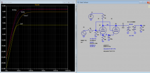
This sim attempts to show the effect of Rp on frequency response. With lower Rp when the coupling cap value is increased so the frequency is extended but a high Rp tube can not. If the cap is too small an amplitude peak at low frequency will show up or kind of resonance, increase coupling cap flatten and extended the bottom freq. response. In other word try to shift the pole downward so it does not interfere with bass reproduction.
Attachments
First get some real and proper test equipment.
Set up realistic connections:
1. A known signal source and a splitter to both the preamp input and one test equipment channel input [signal source needs to have a known output impedance versus frequency, and should be the same output impedance versus frequency as the actual music signal source (like a CD player)].
I have a really good test CD with 21.5Hz, 40Hz, 100Hz, 1kHz, 3kHz, 10kHz, 16kHz, and 20kHz sine waves, at DAC full scale output.
These spot frequencies are all you need.
Do not do a sweep frequency test.
(Most people do not know how to properly set sweeps up, including using different measurement filter bandwidths at different ends of the 20Hz to 20kHz frequency range; and proper sweep times (much much longer times at low frequencies).
2. The preamp output and a splitter to both the power amp input and to the other test equipment channel input.
1. Plus 2. Will tell the frequency response of the preamp, when it is Both:
driven by a specific impedance versus frequency,
and the preamp output when it drives the input impedance versus frequency of the power amplifier.
Be very sure to use the exact same cables from the signal source to the preamp, and the same cables from the preamp output to the power amp;
(The same means the cables that are used are the same for testing, and for listening).
Making calibrated electronic measurements since 1959 (me).
Please understand that tubes are voltage devices - not current devices.In my last post I put a link with measurements fone on 6n6p where you have also the Rp parameter...As you can approximate from the available graphs you could go easily with 2kohm load at 16mA anode current so you'd lower the B+ with just 20 V. A spice simulation can give you the exact value.Try 2k2...1k8 load, 180 ...220ohm cathode resistor.
So lowering anode voltages to abnormally low values even for the transistors, is absolutely wrong way.
Anode voltage for this tube is already wrongly low. Please take a kook at the anode curves and data sheet.
.
It is totally unclear what is the circuit what is the load, is the hating OK, and so many other things
Judging from the "handwriting" of the schematic owner is probably is without experience in this area. Judging of values from the sch, designer of the preamp have not much experience too.
.
So take a care...
It is abs(wrong) test. Because The final load after Coupling C is way too small 5Kand the difference between1u, 10u and 100uF at driving split load
The circuit output resitance as generator is about Ri II Ranode-load
You terminate high generator internal resistance with small load of 5K
producing the high compression-limmiter-dumping effect and loosing almost 6db half of amplified
signal...
in the same time talking of value of Ccoupling to very wrong Rtermination for LF frequency response...
.
This 5K is even smaller because the some R is at the input of next stage. So this
Yes but with wrong settings, it is more waste to use the matched sections tube.The 6N6 and the sister 6H30 are a very good tubef IF correctly selected to get the two setion equals. The selection needs to have a good batch of tubes, unfortuntely.
The costs are reasonable for 6N6 but no so good for 6H30.
When properly set in a circuit both give a high level results.
Of course the filament current is high but can't be a problem.
I using the 6H30 also for a long tail phase splitter, not so easy to trim but very linear and great swing ( keep almost at the limit of specs)
Walter
That's all fine and dandy but quite involved for the pourpose. We don't want to characterize an amp for space flight.First get some real and proper test equipment.
Set up realistic connections:
1. A known signal source and a splitter to both the preamp input and one test equipment channel input [signal source needs to have a known output impedance versus frequency, and should be the same output impedance versus frequency as the actual music signal source (like a CD player)].
I have a really good test CD with 21.5Hz, 40Hz, 100Hz, 1kHz, 3kHz, 10kHz, 16kHz, and 20kHz sine waves, at DAC full scale output.
These spot frequencies are all you need.
Do not do a sweep frequency test.
(Most people do not know how to properly set sweeps up, including using different measurement filter bandwidths at different ends of the 20Hz to 20kHz frequency range; and proper sweep times (much much longer times at low frequencies).
2. The preamp output and a splitter to both the power amp input and to the other test equipment channel input.
1. Plus 2. Will tell the frequency response of the preamp, when it is Both:
driven by a specific impedance versus frequency,
and the preamp output when it drives the input impedance versus frequency of the power amplifier.
Be very sure to use the exact same cables from the signal source to the preamp, and the same cables from the preamp output to the power amp;
(The same means the cables that are used are the same for testing, and for listening).
Making calibrated electronic measurements since 1959 (me).
We just want to verify the LF part. Just a few points would suffice.
Input 100mV signal at 1kHz at the input of the preamp, measure the output at the (loaded) power amp output. Jot that down.
Then measure at 20Hz, 50Hz, 100Hz, 500Hz, jot that down.
Tell us what you measure.
Can all be done with a simple signal source and an AC voltmeter or DMM.
Jan
Got you Boss! You'd be so right if you wouldn't be so hasty at throwing mispelled remarks ... I started to use 6n6p tubes 3 years before i've done any simulation...6n6p can be loaded with a 2k anode load with ease...it is used to drive 32 ohms headphones too...I first put a link to a russian site with real measurements of that tube ...is the hating OK, and so many other things
So take a care...
I just wrote some facts. Didnt said anything offensive please read again.Got you Boss! You'd be so right if you wouldn't be so hasty at throwing mispelled remarks ... I started to use 6n6p tubes 3 years before i've done any simulation...6n6p can be loaded with a 2k anode load with ease...it is used to drive 32 ohms headphones too...I first put a link to a russian site with real measurements of that tube ...
You have to make the difference on Anode Load and Output Load.
Yes Anode Load could be 2K BUT tube has a parameter called Internal resistance.
Anode load RL and internal resistance of the tube Ri are factors deterninating source resistance/impedance
it is roughly parallel result RLoad II Rinternal
Rinternal is about 2.4K
In this case when RL is about 2K Source resitance aas generator is 2.4K II 2K = 1.09K
Terminating this 1.09K with 5K is giving a loss and create disaster for sound outcome...
termination resistor, including stge termination+Rinput of the next stage, should be around 100X source resistance
in this case minimum 110K
not 5K
driving 32 ohms, with Tube loaded with pure resistive anode load of 3K is wrong...
That deserves impedance matching transformer.
.
Loading the tube with transformer is totaly different thing then Anode load resistor.
You must simply understand this.
As other members told @Veeren, pages before this is reactive kind of load, not reistive, and for low frequencies inductance of primary is factor.
.
But it is not clear after so many pages what is the configuration 🙁
.
And I think That @Veeren didnt check the heater supply as some member told him before... 🙁
.
On this forum You can find more informations on 6N6P
like
https://www.diyaudio.com/community/threads/6n6p-tube-focus-on.201362/
.
For headphone of 32ohms driving, step-down transformer with ratio of 8.7 : 1 is welcome.
Tube have gain of less than mju=15.5 X
So it will be rougly 15/9=1.67 total gain of stage. With say 2Vp-p input You will have not more than 3.33Vp-p to headphones.
Should be checked is this enough.
.
cheers
🙂
Last edited:
If you aim at a highly linear circuit based on 6n6p, how are you going to get that "warm" sound?
A highly linear circuit based on tubes can sound as clinical as lm4562...
A highly linear circuit based on tubes can sound as clinical as lm4562...
Last edited:
You cant get the harmonic configuration as LM and others, because they ephesize 3rd Harmonic and other odd h
6N6P and other linear tubes are pointing at even 2nd H with odd 3rd and even 4th in the say natural e decreasing order
there will be no other Hs with normal input signal not larger from -Ug.
.
Please put in the simulation not impedance ratio but inductance ratio. For make it clear what is happening at low end.
Main factors are Ccoupling, and Primary inductance, but Ck is also from factor as, value of last C one to Anode R, in the power supply...
And appropriate coupling factor (witch is unknown without measuring and calculating of mutual inductance) For HF end
Last edited:
- Home
- Amplifiers
- Tubes / Valves
- Single 6N6P preamplifier has no bass to speak of...