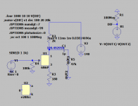
In my last post I put a link with measurements fone on 6n6p where you have also the Rp parameter...As you can approximate from the available graphs you could go easily with 2kohm load at 16mA anode current so you'd lower the B+ with just 20 V. A spice simulation can give you the exact value.Try 2k2...1k8 load, 180 ...220ohm cathode resistor.Thank you dreamth, this is the kind of information I was looking for, what about the anode resistor or do I only change the cathode resistor?
Last edited:

My calculator says Fc = 4 Hz. Hardly weak bass.Yes, the output coupling capacitor (1uF) does seem a little light for ~40k output loads,
Cheers
Jan
You're right about the frequency range, but about the transformer's impedance not only that it can be lower than 40k , but it actually needs to be in the range of the Plate resistor to transfer the right power, be loaded enough and produce the "warm" sound he looks for.
So 5k ohm plate resistor needs an equal transformer impedance to match the 2k5 lightest load of a properly biased 6n6P.
If he's looking to get all the sound from the resistive loading of the 6n6p , then he might need to go as low as 1.5k ohm anode resistor and let the 1uF cap enjoy driving a 40k primary load.Still a 10uF cap would be better in terms of distortions , but there's a bit of a problem in the fact that he will need an electrolitic coupling capacitor if he goes cheap.
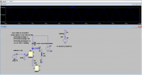
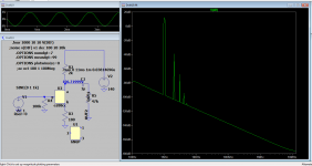
Actually measuring (not "simulating") frequency response would solve this mystery.
Add to that driving the stage hard until it reaches clipping or signal becomes visibly modified (asymmetrical - peak rounded either way - etc.) in both configurations and comparing results, etc.
The old "roll up your sleeves and work" method.
What our forefathers who created Hi Fi did in the 40s 50s 60s.
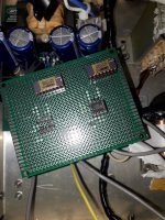
Posting actual screen captures, meaning actual scope screens "captured" with a camera would be great.
Simulation is great, a powerful tool, but work with models (duh!) which may not describe well the actual piece of glass, metal and vacuum we have plugged in our socket at this very moment.
"Weak Bass", to be so clearly perceived, must be significative and well within the audible range, not " -0.5dB@10Hz" or similar.
Add to that driving the stage hard until it reaches clipping or signal becomes visibly modified (asymmetrical - peak rounded either way - etc.) in both configurations and comparing results, etc.
The old "roll up your sleeves and work" method.
What our forefathers who created Hi Fi did in the 40s 50s 60s.
Posting actual screen captures, meaning actual scope screens "captured" with a camera would be great.
Simulation is great, a powerful tool, but work with models (duh!) which may not describe well the actual piece of glass, metal and vacuum we have plugged in our socket at this very moment.
"Weak Bass", to be so clearly perceived, must be significative and well within the audible range, not " -0.5dB@10Hz" or similar.
But I like to remind everyone that my other preamplifier with 12au7`s in paralel has no problem driving this load.
The 12AU7 circuit has the same cap value as coupling?
It seems thet eh Zin at low frequency if trafo is not so high
Walter
Output capacitor is 1µF load is 40k Ohm it is a transformer.
Since the cap is driving an output transformer, the 40k reflected impedance is meaningless if you don't know the primary inductance. As other member suggested, the likely case is that the inductance is too low. You either have to increase the value of the coupling cap or use a different transformer. Do you know the primary DC resistance if you don't have an inductance meter. It can give you a clue. It should have close to or over 1K ohms DCR, the higher the deeper the bass. Or just remove the output transformer and listen to the differences and results.
Hello Walter the parallel 12au7 circuit has a .47µF output capacitor.The 12AU7 circuit has the same cap value as coupling?
It seems thet eh Zin at low frequency if trafo is not so high
Walter
Thanks directdriver I love my Dual EDS 1000-2 direct drive motor!Since the cap is driving an output transformer, the 40k reflected impedance is meaningless if you don't know the primary inductance. As other member suggested, the likely case is that the inductance is too low. You either have to increase the value of the coupling cap or use a different transformer. Do you know the primary DC resistance if you don't have an inductance meter. It can give you a clue. It should have close to or over 1K ohms DCR, the higher the deeper the bass. Or just remove the output transformer and listen to the differences and results.
As my other preamp with parallel 12au7`s does not have the same bass deficiency I don`t see a problem with the transformer .
The DC R of the transformer primary is 750 Ohm
The input impedance of the power amplifier without the transformer would be around 2k2 Ohms...
Last edited:
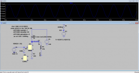

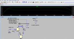

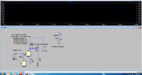
In attach the 6N6 curves taken with my Sofia, one of many I have tested.
In thiw picture there are the curves of both triodes so you can study the different bias.
I think that a 12-15 mA is a good choice
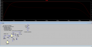
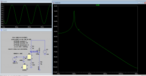
If you have a good sound card with ARTA o Rew software you can check the real frequency anser
Walter
In thiw picture there are the curves of both triodes so you can study the different bias.
I think that a 12-15 mA is a good choice
If you have a good sound card with ARTA o Rew software you can check the real frequency anser
Walter
Attachments

Last edited:
Thanks dreamth and Walter, I think I will use the 180 Ohm cathode resistor and listen to what it sounds like.
Dreamth, what will be the influence of the cathode bypass capacitor of 100µF that was is the circuit and the 470µF capacitor
that I later used?
Again thanks to everyone for helping me out!
Dreamth, what will be the influence of the cathode bypass capacitor of 100µF that was is the circuit and the 470µF capacitor
that I later used?
Again thanks to everyone for helping me out!
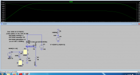
Higher gain and higher probably unwanted distortions.Dreamth, what will be the influence of the cathode bypass capacitor of 100µF that was is the circuit and the 470µF capacitor
that I later used?
You have about 5x gain with no capacitor which I think is ok in most situations of adapting let's say a phone to an amplifier.
You need that bypass capacitor inside a feedback loop, not in a no feedback arangement.
With 100uF you will have a Ft higher than 470 uF in the bass region (with same value of Rk) but it will be not a problem because the the Ft will change of few Hz, but you can check the sonic changes ( in case)
And, very important, you will have a less Zout of circuit tha help for coupling; more gain; more Thd ( little percentage, the 6N6 is linear)
And, very important, you will have a less Zout of circuit tha help for coupling; more gain; more Thd ( little percentage, the 6N6 is linear)
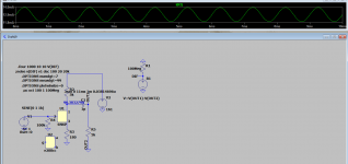
1) No doubt, but 6AU6 is one of 20 parts involved.6n6p spice models are pretty accurate.
2) "Parts may be fine, implementation not so much"
Grounding here instead of there , 1 inch away, is not even considered in simulation, nor in/out wiring layout, etc.
3) circuit/schematic may be fine, but there may be a build error, a misread part, etc.
Only way to catch this suspect preamp with certainty is to plain measure it.
4) asking for actual tests or measurements is like pulling teeth around here.
5) Lamented Enzo many times said: "never search for excuses NOT to check something"
My first circuit based on 6n6p runing at 16mA was first built and measured in march 2014.I also used e288cc and learned that e288cc have better matched diodes, but performs and measures the same overall. I started to learn using simulations only in november 2015 .When I first saw a simulation giving identical results with AP system ONE at 0.002% thd I became a simulation fan.That doesn't mean I don't appreciste measurements, but I can't thank enough to the guy who paid me to learn a bit of LtSpice! Tell me how many guys you saw using two different shielded wires for power gnd, signal gnd and V+, V-? when testing an NE5534?
Attachments
- Home
- Amplifiers
- Tubes / Valves
- Single 6N6P preamplifier has no bass to speak of...