Let me get this right.....A nice design, 😎 just a bit complex
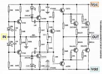
This is a fully balanced amp that does BTL (Bridged) and only takes the NFB from the 15K going to the HOT (+) output? Does the other output (-) follow but in the opposite direction despite not having a feedback connection to it?
Does the fully balanced design reduce THD% by having a more equal swing?
double NFB (hot and cold)
yes it's a fully balanced BTL with unbalanced input
"Complementary Tandem Current Mirror"
good idea have twice NFB but where it's possible connect?
isn't with balanced input😕
yes it's a fully balanced BTL with unbalanced input
"Complementary Tandem Current Mirror"
good idea have twice NFB but where it's possible connect?
isn't with balanced input😕
Re: there is an upgrade if you like
Output TRS. are too close!
Regards zeoN_Rider
Stee said:
Output TRS. are too close!
Regards zeoN_Rider
Stop here upgrade
http://www.esafono.it/easymag3 definitive.jpg
to have two correct NFB need twin complementary MIRROR
and balanced input
Version 3 definitive may be is innovative enough...
...from Motorola what do you recommended in first stage input?
2N5551/5401 as a friend before?
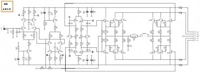
architecture
dimensioning
components
finished
http://www.esafono.it/easymag3 definitive.jpg
to have two correct NFB need twin complementary MIRROR
and balanced input
Version 3 definitive may be is innovative enough...
...from Motorola what do you recommended in first stage input?
2N5551/5401 as a friend before?
architecture
dimensioning
components
finished
PCB and design file
if you like to have PCB of definitive EasyMag3
also for The Gerber Files
based on two innovative method:
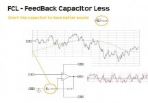
FCL Feedback Capacitor Less
TCM Tandem Current Mirror
ask to Doctor Jan
www.audio-innovation.eu
😉
if you like to have PCB of definitive EasyMag3
also for The Gerber Files
based on two innovative method:
FCL Feedback Capacitor Less
TCM Tandem Current Mirror
ask to Doctor Jan
www.audio-innovation.eu
😉
Re: Re: again about op-amp driver
Foijca is right, his schematic is an unconventional feedforward-error-correction.
I think it is correct and very interesting to test
fojica said:
hi, Stee
i guess maybe it's a bit tricky...but....this is not a traditional class AB amplifier, it's current dumping principle. that means existence of an alternative current bridge...and R10 is part of that bridge, composed by R10-C3-R11-L1. accuracy of the bridge has pretty big importance on amplifier response, so R10 can't go...this is my point of view after reading some documentation about Quad405 and current dumping principles.
please correct me if i'm wrong.
also the op-amp don't drive speaker directly (DC-mode), because there is C2 and JP1(jumper)...C2 is not really needed because original schematic had 741 as op-amp,and the 741 needed some correction...but for TL071 it's not the case. so, JP1 can be in "open" state and then is no direct connection between op-amp and speaker. in fact, JP1 is currently open in my case (his short/open state influence i found being null so far). if it useful somehow i can give the original link, where can be found original schematic and also some details about that one posted by me.
regards,
Tibi
Foijca is right, his schematic is an unconventional feedforward-error-correction.
I think it is correct and very interesting to test
@pintur
thank you 😉
indeed, as i've already said, that amp was built by me for the same scope (test)...and it was a surprise because sound is pretty detailed and dynamical. it's not tiring to listen, also not too bright or too mild.
mine was supplied by +/-38V.
i didn't try to change TL071 for a better amp, maybe it can provide a better sound this way.
if you want more info about that amp, please tell me.
off-topic: right now i'm building another current-dumping, info in this thread: http://www.diyaudio.com/forums/showthread.php?s=&threadid=124348
regards,
Tibi
2 little ideas
Hello everyone,
I have 2 remarks concerning these designs :
1) About the free running mode : to create a floating ground between the power supply rails is forcing the signal into these caps right?
Audiophiles don't like caps, especially huge electrolytic ones with value decreasing with time and non linear behavior (hysteresis at least). A
little one in the NF loop does sound better to me. Anyway, why bother since last moment tweaking will easily reduce the DC output to less than 200mV? I never used any cap in my NF loops before...
2) How could the design with the opamp be a feed forward? It's current dumping for sure but the opamp is to low in power to correct the dumper errors. Furthermore, the feedforward amp should be a class A one because his primary aim is to correct the main type of distortion NF is unable to correct in a class B design : cross-over distortion! That's also why the dumper should be a strict class B or slight C device, if the crossover and switching phenomenon occur for a too high output voltage, it's putting more strain on the power limited class A amp.
I hope my remarks are right.
3 universal quality together
Hello
in the various experiments described I think I have generated some confusion ...
as we know when it is possible to have every stage in perfect complementarity
the sound improves ...
(for example with the stadium entrance is an OP-AMP the rest is symmetrical)
improves the sound even when you have two amplifiers working together but in opposite phase...
(it's worth recalling that the configuration AB bridge or balanced involves the simultaneous activation and superimposed channel N and P as in Class A)
what I discovered (about Nelson) and I ask you to test on your amplifier (be cautions - start with a resistor on output)
is that eliminating capacitors in the circuit
improves the sound so very significant
the use of capacitors output was only a caution!
shorting the condenser of feedback with a resistive load instead of the speaker
you realize immediately that the gap permanent of direct current in output
there are negligible
in case of configuration to bridge this stable component halves
that's why I developed the tandem mirror system:
1 -to have an input absolutely complementary (something impossible with the OP-AMP)
2 -to have a balanced output (then with a DC-Offset minimum)
3 -and of course playing with a clean feedback (the Feedback Capacitor Less method may be is not my invention)
try to beleve if I say the true
keep in mind that these qualities are valid for each amplifier (universal)
do not need a particular schematic🙁 🙁
Attachments
Thank you for your answer,
I understand your point of bridging. I'm not a big fan of bridging but why not. About the use of LTP as VAS stage, Douglas Self showed it's not the optimal configuration but there is nothing really wrong with it. The biggest question that arise is about the NF picking point : since the final stage is not included, it will not enjoy the NF distortion lowering. Most part of the distortion in a power amp appears in that final stage so it will stay untouched at the output. Again, it's a matter of choice but why?
I understand your point of bridging. I'm not a big fan of bridging but why not. About the use of LTP as VAS stage, Douglas Self showed it's not the optimal configuration but there is nothing really wrong with it. The biggest question that arise is about the NF picking point : since the final stage is not included, it will not enjoy the NF distortion lowering. Most part of the distortion in a power amp appears in that final stage so it will stay untouched at the output. Again, it's a matter of choice but why?
Regarding the feed-forward amplifier, I guess I didn't look close enough. It looks like a real one. Apologies...
essential quality for true realism (of music)
Thank you for your answer,
Most part of the distortion in a power amp appears in that final stage so it will stay untouched at the output:
true but don't need NFB because don't have gain (in voltage)
the criterion of essential quality suggests not to add components where there is not needed
even if this variation try on your amplifier
you realize that the harmonics increase generously
Attachments
Hello again,
I don't think that this "gain in the last stage" question is relevant for distortion cancellation by NF. The distortion is an added component and is not amplified (unless it comes from the previous stage off course). It's more a question of gain difference between open and closed loop in the overall system leaving headroom for NF.
And even if the overall system has low gain or unity gain, you can still get a powerful NF by adding gain in the NF loop, with the subsequent problem of linearity in the NF loop.
To include both polarity in the NF of your amp, I guess you could maybe loop the (-) NF point to the (+) of the input pair and let the pair make the subtraction. I don't know about the stability problems it could cause but it seems ok to me. The other solution would be to stay with a unique return path and substract before applying the NF to the (-) of the input, with an opamp for example.
I maybe wrong but let's discuss it
may be it's a good idea add two NFB
see this solution from pdf sharing before
balanced input can be hot and cold NFB
the output go to first complementary mirror (inverted input)
http://www.diygene.com/servlet/the-424/Bal-Class-A-Power/Detail
http://www.e-electronica.es/es/diy-....html?osCsid=e54d285cbd537211082b8292162082ba
see this solution from pdf sharing before
balanced input can be hot and cold NFB
the output go to first complementary mirror (inverted input)
http://www.diygene.com/servlet/the-424/Bal-Class-A-Power/Detail
http://www.e-electronica.es/es/diy-....html?osCsid=e54d285cbd537211082b8292162082ba
Attachments
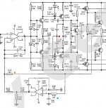

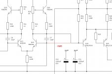
last revision of EasyMag3 Post #78 http://www.esafono.it/Esafono_Tandem.pdf
I think there is very small error at the input of Q 18. The input must be at the base of Q18.
- Status
- Not open for further replies.
- Home
- Amplifiers
- Solid State
- Simply the Best - LiveWave AMP