Looks like there is something wrong with the UBIB. Since the voltages are ok, if you have it already inside an enclosure, could you check if the mosfets of the UBIB are properly isolated from the enclosure?
Have you connected the signal & grounds ok, as per build guide?Hi.
I made the Ultra FSP (Tea Bag kit ).
Everything works but there is too much noise, it is much more important than the background noise of the vinyl, and it is incompatible with classical music.
If I replace the UBIB 1.3S power supply by a battery (34V), the noise is ok.
If I replace the UFSP RAW PSU PCB by a battery (38V in -> 32V out) it doesn't change anything.
I can set all voltages correctly from 30 to 34V for the UBIB 1.3S output, and 4V on the Ultra FSP.
I have a Phasemotion MC200 MC cell (4 Ohms 0.3mV).
Can you indicate me some tests to make on the UBIB 1.3S power supply ?
Best Regards.
Mine is silent like a tomb.
Thanks for your reply,
The mofsets are insulated, I didn't put a thermal tab on at first, I added it later, it doesn't seem to me that they got very hot.
I tried with and without ground, it doesn't change anything, the noise doesn't sound like a badly connected ground noise, more like white noise.
Are there any voltages to check?
Should I check the transistors?
The strangest thing is that the 2 channels make the same noise.
My gain setting is :
MC 56dB
S6 ON S10 ON all others OFF
RX1 ON all others OFF (100 Ohms / I have more noise with more Ohms)
MC 56dB
S6 ON S10 ON all others OFF
RX1 ON all others OFF (100 Ohms / I have more noise with more Ohms)
Check Vgs (DC volatge between pins 1&3) on each Mosfet. Normally 3-4V in this.Thanks for your reply,
The mofsets are insulated, I didn't put a thermal tab on at first, I added it later, it doesn't seem to me that they got very hot.
I tried with and without ground, it doesn't change anything, the noise doesn't sound like a badly connected ground noise, more like white noise.
Are there any voltages to check?
Should I check the transistors?
The strangest thing is that the 2 channels make the same noise.
The voltages are :
In 43 V
out 34 V
M1 4.4V
M2 2.6V
it's the same on both sides
I have tried with 40V and 38V in, there are some small variations of noise.
In 43 V
out 34 V
M1 4.4V
M2 2.6V
it's the same on both sides
I have tried with 40V and 38V in, there are some small variations of noise.
Vgs you report implies the Mosfets work. M2 bit low but it can be due to its small bias current in this. Use an AC mV meter on the DC outputs. See if it catches noise on the rails. Use a scope instead if you got one. AC coupling mode 10mV resolution. Even better for the purpose.
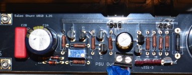
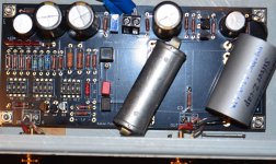
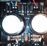
Can you post a hi-resolution picture of the Raw supply, UBIB and the UFSP? A lot of times someone on here will find your issue very quickly.
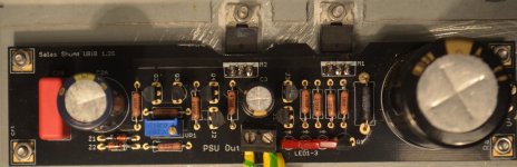
By the way put a thin tie wrap around C3, squeeze a wire between it and the Aluminum sleeved barrel. See it makes a good contact. Regular solder does not make a good bond on Alu but the tie wrap will work. Ground the wire's other end. Russian FT caps tend to attract RF on their metal sleeve. It should not touch any pads underneath it either.
I can measure :
0.03mV at UBIB input
0.017mV and 0.027mV output.
(I can't see the units on my very old METRIX / and I don't measure anything with my newer voltmeter, I'm not sure of the units).
I think I'll have to buy a good voltmeter and an oscilo...
grounding the caps doesn't change the noise
0.03mV at UBIB input
0.017mV and 0.027mV output.
(I can't see the units on my very old METRIX / and I don't measure anything with my newer voltmeter, I'm not sure of the units).
I think I'll have to buy a good voltmeter and an oscilo...
grounding the caps doesn't change the noise
Miniscule mV AC on the rails. Probably the meters own play.
Keep the grounding wire on those cap sleeves. It wasn't meant to solve this particular problem but it works even better when it will be normal.
Keep the grounding wire on those cap sleeves. It wasn't meant to solve this particular problem but it works even better when it will be normal.
The boards look ok in general. I now wonder if its something wrong with the transformer.I'm sending you the pictures
Also for your Phasemation PP-200 0.3mV cartridge try:My gain setting is :
MC 56dB
S6 ON S10 ON all others OFF
RX1 ON all others OFF (100 Ohms / I have more noise with more Ohms)
LoMC 62dB
S5 ON S6 ON S9 ON all others OFF
Just in case some switch is stack doing something weird. Anyway its a more proper gain for such a cart when your phono build will be debugged.
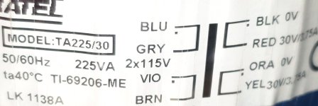
The transformer is a NORATEL 235VA 2x30V that I took from another project.
I also tried a HAFLER TA1600 transformer.
There is always noise when I connect a battery before the UBIB.
If I replace the UBIB with a battery, there's much less noise and it's acceptable.
I tried the LoMC 62dB configuration / S5 ON S6 ON S9 ON all others OFF, it doesn't change much.
I've made some bad combinations with the switches (first I set everything to OFF), is it possible to damage the transistors this way?
All OFF would not create bias in the phono channels input sections and there would be no signal. So a wrong state but not a dangerous one.
Since the shunt supplies are adjusting DC out but even if with battery input they make noise see if details are good like there is 0.6V voltage drop across R1 and if their Q2 Q3 have about 0,6V Vbe too. It really takes some expert scope detection testing for oscillations and noise on dummy loaded shunt regs to confidently debug. But lets do the method of elimination for bad components with spot voltage checks that we can for now.
Since the shunt supplies are adjusting DC out but even if with battery input they make noise see if details are good like there is 0.6V voltage drop across R1 and if their Q2 Q3 have about 0,6V Vbe too. It really takes some expert scope detection testing for oscillations and noise on dummy loaded shunt regs to confidently debug. But lets do the method of elimination for bad components with spot voltage checks that we can for now.
Those got four wire independent 30V secondaries? Is the Raw Supply standard? Center tapped doesn't work for the particularly configured shunts.The transformer is a NORATEL 235VA 2x30V that I took from another project.
I also tried a HAFLER TA1600 transformer.
Those got four wire independent 30V secondaries 30V theoric / 33V mesured for the NORATEL, and a lower voltage for the HAFLER.
It is Raw Supply standard.
Center tapped doesn't work for the particularly configured shunts ??? I think it's ok, I send you some pictures :
It is Raw Supply standard.
Center tapped doesn't work for the particularly configured shunts ??? I think it's ok, I send you some pictures :
Attachments
- Home
- Source & Line
- Analogue Source
- Simplistic NJFET RIAA