Salas & Co.:
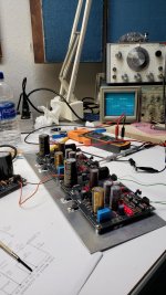
Well, I screwed up big time. The right channel on my UFSP has died. I'm not sure if I damaged things while working on correcting my ground issues or if the problem was caused during construction (it was working fine for the first few days). The solder joints all appear to be fine and the parts are all in the right place and oriented correctly. The only diagnostic equipment I have are DVMs.
There's 34 VDC at the UBiB boards and all of the LEDs light up nicely. I'm sorry to put you through this, but can you suggest a course of action?
Much appreciated,
Scott
That's not fun.
I would print off schematic of both boards, and measure voltages probably starting with the output of UBIB. if that's at 34v, then that's assumed good.
Measure testpoint, voltage across the R2-R3, etc. where the dip switches are on. Make sure they really are on.
Right down voltages across each of those devices and report back or screenshot that.
I have yet to kill any jfet's, so maybe a bipolar or mosfet, or TP is simply not in good range.
Tea-Bag:
An excellent start -- thank you. I'll begin this afternoon and report back.
Regards,
Scott
An excellent start -- thank you. I'll begin this afternoon and report back.
Regards,
Scott
Scott, is it possible that one of either the input or output wires are not actually in the euroblock setscrew connector - the only reason I mention it is I've sometimes thought I had the wire in correctly but it's actually underneath the two pinch plates. Just a thought since it sounds like everything is powering up ok.
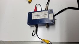
I noted the value of C2 as measured by tea bag and added c2y at 330PF . The inverse RIAA was built from a article published in Audio Amateur. I have been through several phono preamps over the years and this by far is the best yet.
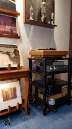
Great results congrats! I can see a DCG3 on your rack but what is the rest of your system? Great tubes decor and beautiful record shelves by the way.
Tea-Bag:
An excellent start -- thank you. I'll begin this afternoon and report back.
Regards,
Scott
Scott no worries, you will fix it. See also if its reversed signal wiring muting at GND.
P.S. See about pressing JFETs in place too if using test sockets for Q1 Q2.
Salas I have the second transformer and 150pf in C2Y. It's been up and running for 24+ hours now. The sound is exquisite, solo piano really shines. I noticed some passages that previously sounded just slightly off on the note attack are now spot on and real.

Elsheadphone the tube art on your wall is beautiful.
Elsheadphone the tube art on your wall is beautiful.
Excellent! Interesting its quiet enough to can hear subtleties while unboxed on 98dB/SPL/W ALTECs.
BTW, what RAW DC Voltage your 30VCT transformers achieve?
BTW, what RAW DC Voltage your 30VCT transformers achieve?
I will have to simulate it for studying its details but it seems like it worked pretty good in practice.
square wave
The system consists of a VPI HW19 turntable with a Zeta tone arm and Sumiko Bluepoint Special. I am using a electronic crossover to a set of Audio Concepts Saturn subwoofers with a pair of 160 watt mobo blocks. The hipass is fed to a Aleph J ( wonderful power amp ) to a pair of Stentorian by Speaker design works.
The system consists of a VPI HW19 turntable with a Zeta tone arm and Sumiko Bluepoint Special. I am using a electronic crossover to a set of Audio Concepts Saturn subwoofers with a pair of 160 watt mobo blocks. The hipass is fed to a Aleph J ( wonderful power amp ) to a pair of Stentorian by Speaker design works.
BTW, what RAW DC Voltage your 30VCT transformers achieve?
44.5 VDC. I'm suprised at how quiet everything is too, no hum or interference that I can perceive. The TT has a 3 prong power cord and there is continuity between the ground on the cord and the ground wire that travels with the signal cables.
RAW DC level is fine. Healthy transformer outputs on healthy mains it seems. I would be inclined to keep any grounding scheme the TT likes best.
@ Scott
See also if Q5 has about same VDS voltage as in the good channel. I have seen broken Q5s in occasions when connecting and disconnecting the FSP output live to gear with much difference of chassis reference voltage. Because you mentioned losing a channel while going over grounding schemes.
See also if Q5 has about same VDS voltage as in the good channel. I have seen broken Q5s in occasions when connecting and disconnecting the FSP output live to gear with much difference of chassis reference voltage. Because you mentioned losing a channel while going over grounding schemes.
- Home
- Source & Line
- Analogue Source
- Simplistic NJFET RIAA