@Andrew
1K91 + 50R signal generator = 1K96 total
1K96 - 600R signal generator = 1K360
1K91 + 50R signal generator = 1K96 total
1K96 - 600R signal generator = 1K360
Last edited:
And do not forget the impedance of the phonestage( 47k for MMstage) at the output.
In all the papers they talk about signal generator impedance but they forget the impedance at the output.😎
question: wouldn't it produce higher precision to just create a RIAA with R5 trimmable so it can be calibrated for the specific generator for max accuracy and then buffer out the output of the RIAA with precision OP-AMP in Buffer configuration so that you take out the uncertainty of the input stage?
You can't have a precision number on input stage impedance and also it can fluctuate over the measured band. With a buffer you have much more precise results IMO and you can swap any phono stage without worrying about input impedance.
Good points for when you change your signal generator frequently.
For me i use the same signal generator for decades. And impedance for standard MM is mostly 47k.
For me i use the same signal generator for decades. And impedance for standard MM is mostly 47k.
If the bottom resistor is 600r and you load it with a 100k for Rin of the next stage, then the effective load becomes 596r4
Even using Rin=47k, gives an effective load of 592r4
Even using Rin=47k, gives an effective load of 592r4
Hi,
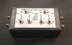
here´s the inverse RIAA I made 10 years ago.
One can switch between 0R, 50R 550R and 600R of source impedance, as well as MM level (-40dB/600R) and MC level (-60dB/60R).
Dimensioning after D. Colins Article "Tweaking the Passive Inverse RIAA Network" in AudioXpress 2007.
Parts are standard metal film and silvermica (stable, low tolerance, quite affordable from Reichelt.de) connected in series-parallel to reduce tolerance.
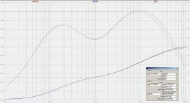
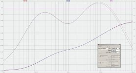
Diagrams show the diversion from ideal response (red) to real(blue).
A nice little gem that proved its useabilty many times. 😉
jauu
Calvin
here´s the inverse RIAA I made 10 years ago.
One can switch between 0R, 50R 550R and 600R of source impedance, as well as MM level (-40dB/600R) and MC level (-60dB/60R).
Dimensioning after D. Colins Article "Tweaking the Passive Inverse RIAA Network" in AudioXpress 2007.
Parts are standard metal film and silvermica (stable, low tolerance, quite affordable from Reichelt.de) connected in series-parallel to reduce tolerance.
Diagrams show the diversion from ideal response (red) to real(blue).
A nice little gem that proved its useabilty many times. 😉
jauu
Calvin
Attachments
@Andrew
1K91 + 50R signal generator = 1K96 total
1K96 - 600R signal generator = 1K360
@Andrew is OK?
yes, use 1k0 + 360r
And look at Calvin's with the optional input resistors.

Measured my turntable today, cables hooked up but without cartridge. The total capacitance 140pf left channel and almost the same in the right channel. Inside my riaa i have 150pf loading at C2Y. So the total is around 290-300pf loading.
My cartridge Nagaoka mp-100 want's less than 150pf according specs.
Can i try without anything at C2Y or is it better to try something like 10pf to come close to 150pf's loading? The riaa and the sound is very good but i like to try if i'm gaining something to come close to the spec of the cart.
My cartridge Nagaoka mp-100 want's less than 150pf according specs.
Can i try without anything at C2Y or is it better to try something like 10pf to come close to 150pf's loading? The riaa and the sound is very good but i like to try if i'm gaining something to come close to the spec of the cart.
C2Y is shaping the HF portion of the RIAA curve, its not an input loading element. Less value gives bit more HF, more value gives bit less HF.Measured my turntable today, cables hooked up but without cartridge. The total capacitance 140pf left channel and almost the same in the right channel. Inside my riaa i have 150pf loading at C2Y. So the total is around 290-300pf loading.
My cartridge Nagaoka mp-100 want's less than 150pf according specs.
Can i try without anything at C2Y or is it better to try something like 10pf to come close to 150pf's loading? The riaa and the sound is very good but i like to try if i'm gaining something to come close to the spec of the cart.
Ok thank's, i'll guess i have to study a bit more🙂 so the C2Y do not add to my 140pf if understand you right. I'll guess the riaa itself add pf? So keep my cables as short as i can maybe lower the total pf. Have 1m cables now.
Last edited:
You understood right. And yes, the input stage itself will add pF. Its cascoded and in MM mode that you use it has enough source pin degeneration resistor value also (local feedback), so its moderate in doing that, but less cable will still be better. There are also some coaxial cables to choose that have less pF/m than others.
Did you box the build by now?
Did you box the build by now?
You understood right. And yes, the input stage itself will add pF. Its cascoded and in MM mode that you use it has enough source pin degeneration resistor value also (local feedback), so its moderate in doing that, but less cable will still be better. There are also some coaxial cables to choose that have less pF/m than others.
Did you box the build by now?
I´m afraid no😱, spent all my money buying vinyls🙂 Have to prioritize to box it soon.
Anyone have an idea what size chassis these are? Would love to mimic this build. From the DIY audio store? Anyone on here?

Sent from my iPhone using Tapatalk
Sent from my iPhone using Tapatalk
they could be 2u high.
https://en.wikipedia.org/wiki/Rack_unit
That would make the front panels ~ 13" wide by 3.5" high.
The little one might be 5" wide.
https://en.wikipedia.org/wiki/Rack_unit
That would make the front panels ~ 13" wide by 3.5" high.
The little one might be 5" wide.
That is my build. Cases are from Modushop in Italy[same as store cases]
The larger cases are 2U high and are 330mmW by 230mmD whist the psu is 124mmWx230mmD.
https://www.modushop.biz/site/index.php?route=product/category&path=67_194_119
Depending where you are it might be easier to buy from the store.
The larger cases are 2U high and are 330mmW by 230mmD whist the psu is 124mmWx230mmD.
https://www.modushop.biz/site/index.php?route=product/category&path=67_194_119
Depending where you are it might be easier to buy from the store.
That is my build. Cases are from Modushop in Italy[same as store cases]
The larger cases are 2U high and are 330mmW by 230mmD whist the psu is 124mmWx230mmD.
https://www.modushop.biz/site/index.php?route=product/category&path=67_194_119
Depending where you are it might be easier to buy from the store.
Thank you for the information!
Do you consider everything a good fit? Are you happy with the internal size for everything? If I could get a shot of psu and boards inside that would be very helpful as well if it is convenient.
Sent from my iPhone using Tapatalk
Something that was rolling around in my head regarding tolerances and matching of the signal caps:
I've noticed a lot of talk about capacitor brands and their attributes, but what in general should we be shooting for in terms of matching between channels and tolerance to the specified value in the SFS BOM? Seems this is discussed far less than the differences between mundorf and obligatto, for instance.
I could very well be wrong as this is a general assumption but it would seem to me that when many are swapping caps to determine their merits some of the changes in sound signature they are describing could be that of the value difference in caps as much as different film cap construction materials?
For example, would precisely matched generic film caps at 2.2uf each channel be a better strategy than silver PIO caps that are 5% off each channel?
What is an acceptable versus non acceptable tolerance and what effect does this have on the circuit and sound? Is there a general guideline to follow?
Sent from my iPhone using Tapatalk
Do you want accuracy or color? Audiophile caps add color. Many of said colors are very beautiful, hence the popularity. This is not, in any way, a bad thing.
Well matched polypropylene caps will get you accurate RIAA and also great sound. This too, is not in any way a bad thing.
Well matched polypropylene caps will get you accurate RIAA and also great sound. This too, is not in any way a bad thing.
- Home
- Source & Line
- Analogue Source
- Simplistic NJFET RIAA