You are welcome. Post a photo of your build & TT when you can.got Tp1 to Tp2= 3.5 volt ,sound freaking awsome with my fidelity research fr-1 mk2 cartridge ,not many phono stage can make this cartridge sing. Thank you
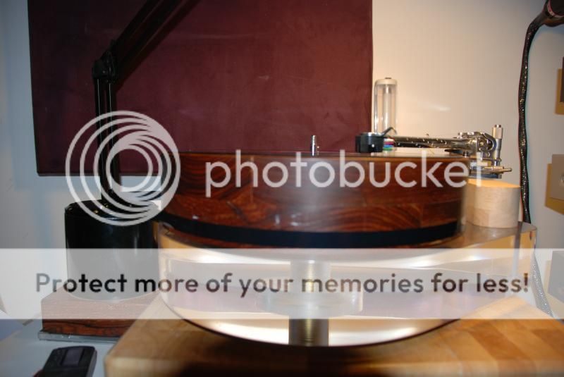
It Teres turntable with audiomod arm,hmm actually a wooden box for the FSP is something to think about ��
Remember to show us your FSP build when ready on the rack. Meanwhile, happy listening. Glad you like it.
Diodes
Hello,
What kind of rectifier diodes are used in the image of the RAW Supply, please?
Rectifier diodes in the image are not MUR or similar, please.
Warm regards,
Ion
Hello,
What kind of rectifier diodes are used in the image of the RAW Supply, please?
Rectifier diodes in the image are not MUR or similar, please.
Warm regards,
Ion
Looking like MSRF860G or similar modern TO-220 diodes. Turbon will inform us the type he preferred. The Raw PSU board provides pads both for axial 1A and TO-220 to choose from a large gamut of available parts.

Yes, Tea got his hands on a pile of these so I wanted to test. At least as good as MUR's.
I'm in the middle of rebuilding parts of my 63db amps so no time for serious A - B listening before the next weekend at the earliest - probably two weeks.
Regards
I'm in the middle of rebuilding parts of my 63db amps so no time for serious A - B listening before the next weekend at the earliest - probably two weeks.
Regards
Hello,
What kind of rectifier diodes are used in the image of the RAW Supply, please?
Rectifier diodes in the image are not MUR or similar, please.
Warm regards,
Ion
They were Fairchild Stealth diodes, 200v 6a I believe. I found them on closeout, so bought a lot of 400 or so.
Don't have any left, have been replaced in my stockpile by standard MSRF860G, partly on Salas recommendation.
Hello Salas
I have two pairs of k369BL 10.4mA idss and I have only 3.9ohm resistors to use as Rs.
Can I use everything as is or do I need to use a different R13 ?
I have R13 = 1k2 Dale 2W
I have two pairs of k369BL 10.4mA idss and I have only 3.9ohm resistors to use as Rs.
Can I use everything as is or do I need to use a different R13 ?
I have R13 = 1k2 Dale 2W
You can use those parts together.Hello Salas
I have two pairs of k369BL 10.4mA idss and I have only 3.9ohm resistors to use as Rs.
Can I use everything as is or do I need to use a different R13 ?
I have R13 = 1k2 Dale 2W
To measure Vf for triplets and quartets, what resistor value should I use for tests if I go to measure all LEDs together connected respectively as 3 and 4 devices with 9V?
My concern is coming up from an empirical test when I measure single LED, then I sum all my measured LED and then I calculating the result. However, I have other result when I measure 3 and 4 LED connected together with the same 1.5K resistor. I assume that LED has own resistance added and this is what differentiate test results.
My concern is coming up from an empirical test when I measure single LED, then I sum all my measured LED and then I calculating the result. However, I have other result when I measure 3 and 4 LED connected together with the same 1.5K resistor. I assume that LED has own resistance added and this is what differentiate test results.
Yes it has. Rtest also needs changing. To get a preciser result from the LEDS when altogether, better connect a 2SK117GR as CCS (G+S together and to first LED, D to +V) from two 9V batteries stringed in series for 18V. No resistors to puzzle you, same current in every test.
Yes it has. Rtest also needs changing. To get a preciser result from the LEDS when altogether, better connect a 2SK117GR as CCS (G+S together and to first LED, D to +V) from two 9V batteries stringed in series for 18V. No resistors to puzzle you, same current in every test.
Got it. I forgot about that....
Thank you a lot.
Thank you Salas.You can use those parts together.
Finally got myself together and did some calc 🙂
Using "Id (ccs) = Idss (1 - (Vgs / Vp))2"
and "Vgs = Id x Rs"
For a K369 idss = 10.3mA and Rs = 3.9ohm I estimate Id = 8.9mA
For both Q1 + Q2 we have a total of 17.8mA Idling
I want 4volts on top of folded collector R4 (2200), so current on R4 is 1.818mA
Total current on R13 (1200) is then 19.62mA
Vdrop on R13 is 23.54V
Having 8V on the folded base we have 8,6V on the emitter of Q3 so we already have a Vdrop of 23.54 + 8.6 = 32.14V
If I set Vp = 35V than I need to drop 35-32.14 = 2.86V on R12//Vr1 for a current of 19.62mA and that gives me 146ohms.
So it seemed I needed to increase R13 or R12/vr1..... but then I remembered you suggested to use alternative Vp.... if I lower Vp to 34v, everything is in place naturally.
Now I only need to drop 1.86V on R12//Vr1 and the resulting resistance is 95ohm.
Quite flexible and brilliant engineering.
Well, I take this long silence like with caution.
Please take in consideration this simulation uses less than perfect fet models so it can only be used to evaluate DC conditions as well as dissipation values in the amp.
It serves no other purpose and I strongly suggest anyone who has any doubts about the circuit should post it here and wait for Salas information.
I can't see the 95r, nor the 146r
Stick the two devices into a plug board and measure the actual voltages.
Stick the two devices into a plug board and measure the actual voltages.
Last edited:
The simulation has slightly different values....
There are only 8V on the emitter of Q3 so Vdrop is 23.54+8=31.54..... this leaves 3.46v to be droped over the resistor ... in this case it is not 146 but 176r (250 // 600).
The sim works ok but as you say the best way is to use a breadboard 🙂
There are only 8V on the emitter of Q3 so Vdrop is 23.54+8=31.54..... this leaves 3.46v to be droped over the resistor ... in this case it is not 146 but 176r (250 // 600).
The sim works ok but as you say the best way is to use a breadboard 🙂
wait for Salas information.
What to say... Its a typical sim. The Jfet models give bit less gain than actual its a remark.
- Home
- Source & Line
- Analogue Source
- Simplistic NJFET RIAA