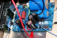
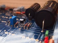
There are a few single wires passing through holes in the separation plate.
You MUST run a Flow and Return PAIR through any hole.
You can run many pairs through the same hole.
NEVER run a single Flow wire, nor a single Return wire, through a metal plate hole and especially of the plate is ferrous/magnetic.
I apreciate your comments Andrew but would you explain your last statement ?
Those singles look like ground reference wires to me.
Those are GND reference wires indeed.

I am considering as a cost saving exercise, using Elna Silmic II caps for DC blocking output caps. Your opinions are welcome on this.
I have been trying to assess film caps suitable for this purpose, mostly by consulting the oracle of Google and reading various subjective listening tests, and my conclusion is that there is a lot of placebo in effect. Audiophoolery, some call it.
Can people tell the difference between a £13 Mundorf Supreme or even a Dudeland cast PIO 2.2uF cap and a 50p Silmic II 2.2uF DC blocker in a "BLIND" test with any degree of repeatability, I wonder? I would be surprised if it were shown reliably that they could.
I'd like to see Andrew's explanation too.
In my understanding, any wire shares a magnetic field with whatever is near it, be it steel or aluminum or just air. A plate that the wire passes through may be magnetic and excited by the transformer, and couple through the magnetic field into the wire. Or it may be aluminum, and chassis currents inducing noise into the wire through the shared magnetic field.
A well-twisted two-wire signal line will have equal voltages induced and therefore the sum will cancel out any noise induced by the magnetic field in the plate. Of course this effect is not perfect and there can still be effects from the currents generated, but a twisted signal-return pair is still far better than a single wire, coaxial would be best for very sensitive inputs. Also of note is that magnetic materials are nonlinear and can cause distortion even if they aren't a source of noise. This is usually only a problem with high-current low impedance loads though.
That chassis looks like it's mostly steel, so the potential for this kind of noise extends to lower frequencies than for aluminum. The single wire going through the panel looks like a ground wire. As long as there aren't any connectors on the front panel, then it would be optimal to route all the wires through a single hole, perhaps even the power input if it is shielded. But if keeping signal and power lines separate is also important, and if the panel is not a larger source of noise, then it may be best to leave it as it is.
I am considering as a cost saving exercise, using Elna Silmic II caps for DC blocking output caps. Your opinions are welcome on this.
I have been trying to assess film caps suitable for this purpose, mostly by consulting the oracle of Google and reading various subjective listening tests, and my conclusion is that there is a lot of placebo in effect. Audiophoolery, some call it.
Can people tell the difference between a £13 Mundorf Supreme or even a Dudeland cast PIO 2.2uF cap and a 50p Silmic II 2.2uF DC blocker in a "BLIND" test with any degree of repeatability, I wonder? I would be surprised if it were shown reliably that they could.
From the blind ABX generic parts all lab objective guys to the sighted AB boutique parts subjective guys the FSP will deliver. Build it in your style and budget by all means.
Here is an interesting video from the subjective camp.
https://www.youtube.com/watch?v=hnezplX1zlc
That chassis looks like it's mostly steel, so the potential for this kind of noise extends to lower frequencies than for aluminum. The single wire going through the panel looks like a ground wire. As long as there aren't any connectors on the front panel, then it would be optimal to route all the wires through a single hole, perhaps even the power input if it is shielded. But if keeping signal and power lines separate is also important, and if the panel is not a larger source of noise, then it may be best to leave it as it is.
In this case power lines carry 220v AC and the nearby amps pick up noise easily so I needed to screen the IEC input with a metal screen and route the mains cabling to the TX throu a dedicated hole.
It works rather well as is.
One of the best scientific research articles in capacitor distortion. I have read it before and its a highly recommended read to those who haven't.
So, after some week of playing, some week of travelling and then some more playing (and a cold from hell) I did some measurment in my temporary case with lid open. There is no ventilation holes under the main sinks atm, they are just standing on some small wood pins so ther is kind of a bad flow from under but then again open lid on top.
I putted one DVM on TP1-2 and the other with 2 temp probes (blue wires). Temp 1 in contact with 369 and Temp 2 with the temp wire insulation on the hottest sink. Ambient temp was 22 degrees C.
Heres my startup sequense (VTP1-2), (Temp 1, (Temp 2):
10s ( 5 ) ( 22 ) ( 23)
30s ( 3,8 ) ( 23 ) ( 24)
1m ( 3,78 ) ( 23 ) ( 26)
2m ( 3,733 ) ( 23 ) ( 29)
3m ( 3,705 ) ( 23 ) ( 32)
4m ( 3,689 ) ( 24 ) ( 34)
5m ( 3,670 ) ( 24 ) ( 36)
10m ( 3,620 ) ( 24 ) ( 41)
15m ( 3,591 ) ( 23 ) ( 43)
20m ( 3,578 ) ( 24 ) ( 44)
25m ( 3,567 ) ( 23 ) ( 45)
30m ( 3,568 ) ( 23 ) ( 45)
So it looks fairly stable over time. It can use some tiny adjustment, but Howe Gelb sounds better then ever right now so that will be for later implementations.
Cheers
Attachments
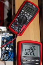
This is the "leave it alone for half an hour to fully warm up" you can find in the biasing section of the pdf guide.
Yours is definitely alright, and its good you enjoy the sound. Congrats.
Yours is definitely alright, and its good you enjoy the sound. Congrats.
The electrician wiring up my house distribution board did not have enough 16mm² double insulated cable to wire up the 4 tails into the Box with him.
I (looking over his shoulder) said, why don't you take the short route, that will save enough cable to let you finish the job?
He said in reply:
"NEVER pass a single wire through a panel and return through a different hole."
I can't recall his short explanation, but it may have been about eddy currents in the metal of the panel that is inside the LOOP.
Any Electricians (or Electrical Engineers) listening?
This is the "leave it alone for half an hour to fully warm up" you can find in the biasing section of the pdf guide.
Yours is definitely alright, and its good you enjoy the sound. Congrats.
Yes thank you! I was curious on the flatting out curves and final stabilised values under conditions that gets closer to my later boxing plans then just with the boards on the table.
It sounds great indeed, both the stage and the 10x5. Totally new dimensions in comparement to my old pro audio card. No surprises but good confirmations so far!
I have looked around
But would like advice please for measuring 170Bl MA Idss for Q4,5 and 6. I got 6 x from Teabag. Very great full for any guidance. Is the rig RCruz the way to go?
I read in another post, short gate to source, 9v battery from drain to source, 10 r between drain and battery and measure across resister. Does this sound right? I'm trying not to screw this up.
Last edited:
That simple way is linked in the guide. Links to an old post by John Curl saying that. He knows that stuff, no worries. You can make the 10R to 100R if your DMM is not too trusty in low mV region. Idss will be Vr(mV)/r(ohm).
Yep that's the one by JC, ok ill give it a go. Getting a little nervous.. 😀, actually getting excited
Attachments
Last edited:
Thanks Salas, yep its getting closer now. I'm still a little confused though with this jfet idss thing, does my pic look right? Do i measure Ma across R, or volts? 🙄
But would like advice please for measuring 170Bl MA Idss for Q4,5 and 6. I got 6 x from Teabag. Very great full for any guidance. Is the rig RCruz the way to go?
I read in another post, short gate to source, 9v battery from drain to source, 10 r between drain and battery and measure across resister. Does this sound right? I'm trying not to screw this up.
Attachments
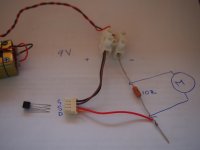
Reverse the battery's polarity. You measure mV across the resistor and you convert to mA using the Ohm's law I=V/R.
- Home
- Source & Line
- Analogue Source
- Simplistic NJFET RIAA