What could have gone wring with the graphite pads? Were they conductive? Capacitive properties?
I'm not sure. The thing is that Q1 drain on both ch. was shorting to ground
once I start tightening it to the sink. Strange that was not the case with Q4-
it stayed insulated from the sink no matter how tight it was. I know that as
my audio gnd is separated from the safety gnd by 10R-2W II 100n NPO.
My meter showed 0ohm Q1 (tightend to sink) to chassis and ~10ohm Q4 to chassis.
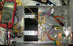
 Tempco behavior is linked to sinking anyway. Mosfets so near together wouldn't be advised in high amperage but at 150mA with those sinks, its a pass I assume.
Yes MOSFETs mange to close to warm 🙂, I'm thinking to drop the value of R1 to get closer to 200mA. Now I'm at 175mA ((LedStringV)5.4V-(VgsQ1)3.65V)/10ohm=0.175A. Any need for that?
Wait until you get your riaa pre together, so to actually test if Hot Rodding the psu will do something audibly positive to your system after you are familiar.
I am seeing a toroidal in the box though, and if you plan an mc riaa it will be a battle with field induced hum.
I'm going for MM riaa, 39dB of gain. I decided to take a risk with toroid and if field induced hum shows as a problem I'll house the toroid outside in a separate box.
If with MM, danger lowers. And you got some distance. A grounded copper band wrapping around the toroid's periphery usually helps a lot also. But before the pre is made we better not worry much.
Fired up today. We have music in both channels 😀 Thank you Salas.
I only have one record at the moment. Even that's borrowed. So I'll be around the charity shops in the next few weeks and see if I can get something to compare with digital.
I will post some pics for you when I've tidied up.
There's some hum too that needs sorting.
Thanks again Salas.
I only have one record at the moment. Even that's borrowed. So I'll be around the charity shops in the next few weeks and see if I can get something to compare with digital.
I will post some pics for you when I've tidied up.
There's some hum too that needs sorting.
Thanks again Salas.
Fired up today. We have music in both channels 😀 Thank you Salas.
I'm not sure. The thing is that Q1 drain on both ch. was shorting to ground
once I start tightening it to the sink. Strange that was not the case with Q4-
it stayed insulated from the sink no matter how tight it was. I know that as
my audio gnd is separated from the safety gnd by 10R-2W II 100n NPO.
My meter showed 0ohm Q1 (tightend to sink) to chassis and ~10ohm Q4 to chassis.
I have some graphite to240 pads. I purchased them (years ago) because of their astoningshly low thermal resistance.
Unfortunaly they are conductive. It was written on the specs.. 🙄
http://search.digikey.com/scripts/D...&lang=en&site=us&keywords=BER131-ND&x=10&y=18
are the ones. I was lazy to check the data sheet so I paid the price 🙂
are the ones. I was lazy to check the data sheet so I paid the price 🙂
I am so surprised how good my £12.50 Technics deck sounds. Salas, your circuit is working great. The music dept, at work is chucking out a pile of classical vinyl, which I have just inherited.
I still have a slight problem with hum. However, it seems that there are quite a few causes of it besides earth loops. I thought I would need to rehouse my RIAA circuit, but maybe not.
I still have a slight problem with hum. However, it seems that there are quite a few causes of it besides earth loops. I thought I would need to rehouse my RIAA circuit, but maybe not.
Show some pics, maybe we can help you with routing and boxing ideas. It's been done silent many times before, there should be a better config.
Do you use coax signal cable? Is a question until you show pics. If not, try that.
I installed screened cable today. I also re-routed the power cables away from the RIAA.
RESULT - hum gone 😀
Good tip, thanks Salas.
I'll still post pics this weekend.
Here's my circuit.
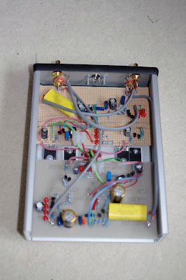
Initially the power input was in-between the audio in and out. This meant that power had to cross one of the boards, which contributed to the hum. Power now comes in from the middle of the base.
Initially the power input was in-between the audio in and out. This meant that power had to cross one of the boards, which contributed to the hum. Power now comes in from the middle of the base.
- Home
- Source & Line
- Analogue Source
- Simplistic NJFET RIAA