I measured 1.9V across the LED in the regulator so I've upped R4 to 1.5k. I have also had to use 6.8 ohm for R1, will that unbalance the CCS circuit? The BJT transistors do run a bit cooler now, but I say still run around 60-70C. Vin is 50.7V on load
~1mA for the cascode is enough. What is your Q4 Vbe? 6.8R for R1 brings less than 100mA CCS, edge low for two channels of phono, enough for one channel. I would give it a 4R3 as a conservative choice. What is your Q2 Vbe?
I'm using one reg per channel.
Sorry I can't tell you the vbe as they are in circuit but the CBE voltages are:
Q2: 51.7,51.1,24.7
Q4: 23.9,1.9,1.4
Sorry I can't tell you the vbe as they are in circuit but the CBE voltages are:
Q2: 51.7,51.1,24.7
Q4: 23.9,1.9,1.4
Anyway they should be around 0.6V at those positions. 6.8R R1 per channel is conservative but fine then. Spare/load ~50/50.
60-70C on the cascode transistors with just~20mW each is weird though. But you say there is no oscillation. Local oscillation could make them hot. Or they are squeezed next to something hot?
60-70C on the cascode transistors with just~20mW each is weird though. But you say there is no oscillation. Local oscillation could make them hot. Or they are squeezed next to something hot?
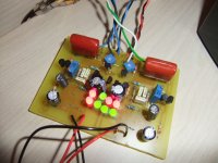
P.S. Read that article and test the loading a bit more first because I mainly afraid the MM cart's termination. Also a photo would be nice.
I've built a PSU LM317 based and played a little bit with loading and found optimal around 35-45k. Also i tried different capacitors but not so much differences in sound so i installed 220pf.
Now the harshness is gone but still sounds clinical, analitic weak bass.
I also tried different capacitors for output cap and the 47nf interstage cap but nothing changed audible.
I want to thank for the pcb layout found in the zip package, helped me not to try to reinvent a new layout.
Attachments
Harshness in mids gone is a good loading result. Time for its remote sensing shunt regulator.
Are the 15n capacitors measured as 15.6n? If they are less, which such caps are usually bellow nominal, then it will be analytical in tonality. Try 1n parallel to them underneath.
Wich config of shunt to use for my 20v povered preamp ?
The one in 10.12.F0 pdf even with TO-220 Mosfets as mentioned in the text. Use your spare GR fet where is asks for. Its trimmer will give you 20V.
On the other side of PCB i've soldered in paralel 680pf.
Ceramic or MKP 680pF? Are the output ones MKT or MKP?
On the other side of PCB i've soldered in paralel 680pf.
Better 1n silver mica if possible.
The 680pf are wima green saved from a defective equipment with 2,5% tolerance. I guess they are FKP2 Polyprop. On them is written W4.
The output ones i dont know what type they are, nothing written on them.
Is that right silver mica is the same with styroflex? I have some 1nf in my drawer.
Like this one : http://www.adelaida.ro/images/Kituri/2009_2/stiroflex-100x80.jpg
The output ones i dont know what type they are, nothing written on them.
Is that right silver mica is the same with styroflex? I have some 1nf in my drawer.
Like this one : http://www.adelaida.ro/images/Kituri/2009_2/stiroflex-100x80.jpg
Last edited:
If there was local oscillation the led should have been rather dim. Is it dim?
No, both channels have the LEDs brightly lit and both measure very similarly.
The 680pf are wima green saved from a defective equipment with 2,5% tolerance. I guess they are FKP2 Polyprop. On them is written W4.
The output ones i dont know what type they are, nothing written on them.
Is that right silver mica is the same with styroflex? I have some 1nf in my drawer.
Like this one : http://www.adelaida.ro/images/Kituri/2009_2/stiroflex-100x80.jpg
No, they aren't the same, mica is a mineral, styroflex is polysterene. But use those 1n you got bcs I am afraid that the real combo value now is below 15n6. The output ones in your pic could be MKT for loudspeakers.
No, both channels have the LEDs brightly lit and both measure very similarly.
If they are lit brightly and you see no oscillation on the rails with your oscope as you thoroughly described, then I have no way to suspect something else. Stick a metal Pi shaped leaf on top of those transistors with some resin to keep them cool at least.
The one in 10.12.F0 pdf even with TO-220 Mosfets as mentioned in the text. Use your spare GR fet where is asks for. Its trimmer will give you 20V.
What means 10.12.F0 ?
- Home
- Source & Line
- Analogue Source
- Simplistic NJFET RIAA