Bad feedback in terms of simply bad, too much or lack of bass?
It's not that I am a fan of huge bass, but at the moment I wish it was a little more present.
It's not that I am a fan of huge bass, but at the moment I wish it was a little more present.
Then the quest is not over. FT-2 is not for me. Spendors are rather slow. Is it the same when it comes to FT-1 and FT-3?
riaa boards finished!
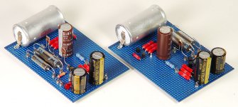
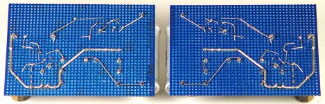
Got the boards wired up (for the most part), attached. I've got R-loads yet to voice and install. The Tex-Caps need trimming; presently at 46.6 and 14.06 nF respectively. Trimmers will piggy-back Tex-Caps. C and R out will be directly soldered to output jack in chassis.
I decided to do mirrored layouts to leave room between the two RIAA boards for big PIO output caps and/or the Maximus Lightspeed attenuator. This keeps leads nice and short.
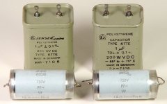
Speaking of output caps- I've got a selection. For all the teflon, some nice vintage PIO's might compliment well. I found these polystyrene caps at ham-fests a while back. Might give them a listen, too..
Next step is to power up, get some readings and look at signals on a scope.
-Kent
Got the boards wired up (for the most part), attached. I've got R-loads yet to voice and install. The Tex-Caps need trimming; presently at 46.6 and 14.06 nF respectively. Trimmers will piggy-back Tex-Caps. C and R out will be directly soldered to output jack in chassis.
I decided to do mirrored layouts to leave room between the two RIAA boards for big PIO output caps and/or the Maximus Lightspeed attenuator. This keeps leads nice and short.
Speaking of output caps- I've got a selection. For all the teflon, some nice vintage PIO's might compliment well. I found these polystyrene caps at ham-fests a while back. Might give them a listen, too..
Next step is to power up, get some readings and look at signals on a scope.
-Kent
Attachments
Got the boards wired up (for the most part), attached. I've got R-loads yet to voice and install. The Tex-Caps need trimming; presently at 46.6 and 14.06 nF respectively. Trimmers will piggy-back Tex-Caps. C and R out will be directly soldered to output jack in chassis.
I decided to do mirrored layouts to leave room between the two RIAA boards for big PIO output caps and/or the Maximus Lightspeed attenuator. This keeps leads nice and short.
Speaking of output caps- I've got a selection. For all the teflon, some nice vintage PIO's might compliment well. I found these polystyrene caps at ham-fests a while back. Might give them a listen, too..
Next step is to power up, get some readings and look at signals on a scope.
-Kent
Congratulations Kent, very very nice & neat work.
What are these small things to connect the components to the pcb?
Attachments
Little through-hole eyelets; my local surplus place had them. I cut the tops to form a fork or "U". Easy to drop in/change/connect stuff without removing the board from chassis.
Thanks Ricardo! I like making tidy layouts- must have been all the old military tube gear I've seen over the years; some of it is darned pretty.
Kent's 2011 Salas RIAA is alive
..and I stayed up to 4AM listening! 😀 Burn-in process has started. About 10 albums so far.
I trimmed the Tex Caps with some vintage NOS mica I had-. The 47nF are just about smack on 47nF. 15.1 nF are around 15.11-15.12nF (if my cap checker is accurate).
Played with Rload- 820 for the start. Sounded a bit thin. Ended up liking the recommended load of 150 ohms (Benz Glider Low).
C-out is a 3.3uF run-of-the-mill M-Cap paralleled with a 1uF Sprague Vitamin-Q. Plenty of bass if I'm running it straight through into the amp. Bass is a bit thin when plugged into a Maximus Lightspeed, as it only has ~7k input impedance. I'll need to add a ~1.5uF to C-out at some point, but I'm fine with it for now.
PSU- Using a lab supply for 48v in. Shunt set to 41v. Only using one shunt for now; the other is waiting for heatsinks to arrive.
Sounds very well balanced and dynamic; I was a little worried all that teflon would sound too clinical. Nope!😀 I did burn in the FT3's for a week, maybe that helped.
Thanks again Salas et all for the circuit and guidance. Wouldn't have been as easy with all of you chaps' help.
Now... to come up with a cool case!
Cheers- Kent
Attachments
Very nice build, and nice component choices too 😀Got the boards wired up (for the most part), attached. I've got R-loads yet to voice and install. The Tex-Caps need trimming; presently at 46.6 and 14.06 nF respectively. Trimmers will piggy-back Tex-Caps. C and R out will be directly soldered to output jack in chassis.
I decided to do mirrored layouts to leave room between the two RIAA boards for big PIO output caps and/or the Maximus Lightspeed attenuator. This keeps leads nice and short.
Speaking of output caps- I've got a selection. For all the teflon, some nice vintage PIO's might compliment well. I found these polystyrene caps at ham-fests a while back. Might give them a listen, too..
Next step is to power up, get some readings and look at signals on a scope.
-Kent
Here is my latest build. It is a 40db version for my Dad for his Lenco with Pro-ject arm and Dynavector 20a HO-MC cartridge. I wanted to build it compact so it is all on one board. The regs are V1, 25V. I will be changing the RIAA capacitors shortly for better types, these are just ones to get it working. It will be installed into the integrated amp I made for him using a diamond buffer circuit and NCC200 power amplifiers. Transformer is from an old Nak tape deck and gives 38V DC for the regs to use.
My next plan is to build another 60dB version for myself, but using V1.2R regs (I do have a scope for testing for oscillation), and also plan to use a single (but larger) board for everything again. Salas - most of my JFets are around 9-9.5mV and I'd struggle to make another using 8.5-8.7 as per the first circuit you recommended me - what changes do I need to make to bias these higher JFets properly please?
My next plan is to build another 60dB version for myself, but using V1.2R regs (I do have a scope for testing for oscillation), and also plan to use a single (but larger) board for everything again. Salas - most of my JFets are around 9-9.5mV and I'd struggle to make another using 8.5-8.7 as per the first circuit you recommended me - what changes do I need to make to bias these higher JFets properly please?
Attachments
Nice. Did you put it into use yet? As for resistors changes with different IDSS let me know your best matches when the time comes so we figure it out.
P.S. What V1 regs are those with TO-220 Mosfets? 1.1 Bib clone, or 1.0 with alternative semis, or the riaa pdf one with the alternative semis as in the guide?
P.S. What V1 regs are those with TO-220 Mosfets? 1.1 Bib clone, or 1.0 with alternative semis, or the riaa pdf one with the alternative semis as in the guide?
I'm just testing it now, the only high output cartridge I have is an Audio Technica AT-110E, so I wasn't expecting much from the cartridge but it really is very, very good! I have just changed the RIAA caps for 47nF and 100nF ERO MKP 1837 and 16nF polystyrene - nothing fancy but still much better than the polyesters. I told my dad I would make something that would easily beat his Cambridge Audio 540P phono stage, I've not compared them yet but I'm sure it is mission accomplished 🙂
I used the layout that Quanghao uses for his boards, I've attached it here. CCS resistor is currently at 47R and the heatsink gets to around 50C after 10 minutes, so I wouldn't want to push it much higher.
I used the layout that Quanghao uses for his boards, I've attached it here. CCS resistor is currently at 47R and the heatsink gets to around 50C after 10 minutes, so I wouldn't want to push it much higher.
Attachments
I've had a look at my J-fets and I have the following in higher values:
8.3-8.5mA - 3
8.6-8.8 - 6
8.9-9.1 - 10
9.2-9.4 - 14
9.5-9.7 - 14
9.8-10 - 7
10.1-10.3 - 14
10.4-10.6 - 15
10.7-10.9 - 19
11-11.2 - 6
So it looks like a design that uses 10.7-10.9 would be best for me. Ultimately I plan to build two of the 60dB phono stages using V1.2R regs for both of my systems, plus any other tips I can use to get the best possible performance.
- Home
- Source & Line
- Analogue Source
- Simplistic NJFET RIAA