From my limited experience and judging by my ears only, I'd say you have a CHAMP there and we are all very lucky to have you not only sharing it on this forum but also helping us out (incl. inexperienced builders like me). So a Big Thanks and Well Done!!
Joe A
You are welcome. It was made as a project with good fidelity to complexity ratio, nothing pretentious, that with some care it can be replicated by enough non engineer enthusiasts. I.e. People like me. Its not for the kit plug n' play construction style either as you saw. Open loop and Jfets need individual gain and bias tunings. Very near to a valve DIYer's experience level for builds OTOH.


Balanced NJFET RIAA
Was a bad layout connection in the cold right channel I modified like the left cold channel & changed also the njfet because was damaged, about sound is clearly better than SE there is more space between instruments & all is with more body it's really & big upgrade if you have the rest of your system full balanced "highly recommended" thanks again Salas for kind & expert support
Was a bad layout connection in the cold right channel I modified like the left cold channel & changed also the njfet because was damaged, about sound is clearly better than SE there is more space between instruments & all is with more body it's really & big upgrade if you have the rest of your system full balanced "highly recommended" thanks again Salas for kind & expert support
merlin el mago: Eureka !!! I'm enjoying balanced Simplistic NJFET RIAA
Hello Felipe, Congrats!! If Salas is the designer of this project and deserves all the credit for it, you must be its most dedicated fan!! You did a very good job of sorting out the various circuits for different cartridges and gain. I can understand how you feel. This project is real fun. I too got hooked on it.
Salas: You tell us more later.
Could you perhaps post a circuit diagram of your Balanced Simplistic so everybody can understand exactly how it is built?
Regards,
JA
Thanks JA for kind words, it's simple & do two stereo Simpistic NJFET RIAA, I used the positives & negatives of each RCA in each of 4 inputs so input gnd is floating, outputs are:
hot output / positive input
could output / negative input
gnd output / gnd star from regulators gnd
If you have any doubt let me know?
Cheers
hot output / positive input
could output / negative input
gnd output / gnd star from regulators gnd
If you have any doubt let me know?
Cheers
Balanced Simplistic NJFET RIAA wiring schematic
Enjoy & have fun
Cheers
Felipe
An externally hosted image should be here but it was not working when we last tested it.
Enjoy & have fun
Cheers
Felipe
AndrewT is balanced input, do you forget the input gnd to chassis? I forgot to tell that my gnd output regs are connected to chassis gnd....remember all output carts are balanced...
An externally hosted image should be here but it was not working when we last tested it.
Last edited:
which is why I ask where are the MM, MC connections in your diagram.remember all output carts are balanced...
You show unbalanced input to balanced output.
Hallo Felipe ,
Congrats ! and thanxs for your pioneering work .
Hope you enjoy the black gold fully .
A big , big thanxs to Salas too for this simple thingie !
Greetings
Juergen
Congrats ! and thanxs for your pioneering work .
Hope you enjoy the black gold fully .
A big , big thanxs to Salas too for this simple thingie !
Greetings
Juergen
Hi Salas ,
me ?
at the moment i am in preparation for the _thousend itterations_ ,
but to lazy to match the J-Fets or not in the mood for soldering .
I would like to see a PCB in the DiyAudio-Shop (not for me) but
for newbees or starters , for such people that have not soldered
anything . Maybe a good oppertunity to spread the gospel of analog
or winning the I-Pod-Generation .
Greetings
Juergen
Hallo Felipe ,
Congrats ! and thanxs for your pioneering work .
Hope you enjoy the black gold fully .
A big , big thanxs to Salas too for this simple thingie !
Greetings
Juergen
Hi Juergen,
Thank you, without Salas & his work never do it, thanks Salas.
Cheers
Felipe
Salas NJFET RIAA PCB
My first knowledge of this very good design was around last summer, at the time I was not very good welcomed, and I went way, although not giving up…
I kept on reading the threads development from the “shadow”.
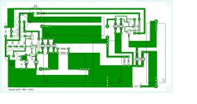
Last weekend, having during this time gathered all the needed material to build my own Salas RIAA, I decided I didn’t wanted to go at it with point to point boards, and decided to design some kind of a PCB board. The result is presented in the jpeg bellow, it was made with the help of PAD2PAD software, I didn’t had time to etch yet but after some analysis I believe it is correct from the electrical point of view.
I thought it to allow the use of several types of resistors, mainly 15mm spaced and Caddock (this includes 1W resistors), for the use of several types of capacitors, like Russian Teflon, Russian silver mica, Lenco, and the possibility of paralleling smaller values to get the final ones right. I had extra careful with the ground path, and will etch with double faced boards, using the top with full copper (of course isolated in all not ground connections).
Attached also is the P2P file.
Please take extra time to re-check and then use it as you please.
I will now work on the Shunt supply.
My first knowledge of this very good design was around last summer, at the time I was not very good welcomed, and I went way, although not giving up…
I kept on reading the threads development from the “shadow”.
Last weekend, having during this time gathered all the needed material to build my own Salas RIAA, I decided I didn’t wanted to go at it with point to point boards, and decided to design some kind of a PCB board. The result is presented in the jpeg bellow, it was made with the help of PAD2PAD software, I didn’t had time to etch yet but after some analysis I believe it is correct from the electrical point of view.
I thought it to allow the use of several types of resistors, mainly 15mm spaced and Caddock (this includes 1W resistors), for the use of several types of capacitors, like Russian Teflon, Russian silver mica, Lenco, and the possibility of paralleling smaller values to get the final ones right. I had extra careful with the ground path, and will etch with double faced boards, using the top with full copper (of course isolated in all not ground connections).
Attached also is the P2P file.
Please take extra time to re-check and then use it as you please.
I will now work on the Shunt supply.
Attachments
which is why I ask where are the MM, MC connections in your diagram.
You show unbalanced input to balanced output.
TT RCA + to input +
TT RCA - to input -
TT GND to gnd input
So balanced input to balanced output.
Andrews point, made by others as well, is that the cartridge output is balanced but not referenced to ground. To get a proper balanced output a center tapped transformer would be have to be used.
Does a Grado cart have balanced output? They are usually wood or plastic bodied so there cannot be a ground reference in them. I do not know of any moving coils with a center tapped coil. For that matter is there any cart with a known center tap or ground independant of the four output pins?
Does a Grado cart have balanced output? They are usually wood or plastic bodied so there cannot be a ground reference in them. I do not know of any moving coils with a center tapped coil. For that matter is there any cart with a known center tap or ground independant of the four output pins?
- Home
- Source & Line
- Analogue Source
- Simplistic NJFET RIAA