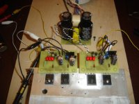
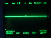
Things are progressing nicely. Attached are a couple of photos showing the Shunt regulator in operation and the scope trace on the output. 2mV/division. Both Channels are a flatline. Can adjust voltage from 25 to 50V. Has held 42.05 +/- 0.05 Volts now for over three hours. This is without a chassis. It is passing 50mA through the dummy load as I only had 750R power resistors with enough wattage.
Thanks Again Salas for a great design.
Thanks Again Salas for a great design.
Attachments

2SKs they are not the best if you want gain in line applications indeed. See about BF862 if you don't mind handling surface mount components. I prefer tubes at that signal level in general.
Thanks Salas, I'm not a friend of surface mounting... I don't want to disturb the thread with a line stage discussion. Can we chat by mail?
Things are progressing nicely. Attached are a couple of photos showing the Shunt regulator in operation and the scope trace on the output. 2mV/division. Both Channels are a flatline. Can adjust voltage from 25 to 50V. Has held 42.05 +/- 0.05 Volts now for over three hours. This is without a chassis. It is passing 50mA through the dummy load as I only had 750R power resistors with enough wattage.
Thanks Again Salas for a great design.

Thanks Salas, I'm not a friend of surface mounting... I don't want to disturb the thread with a line stage discussion. Can we chat by mail?
I am not a circuit specialist, there are excellent examples of line stages in the forum. Better have a look around.
I am not a circuit specialist, there are excellent examples of line stages in the forum. Better have a look around.
What's the best tubes line stage? please could you post the schematic or a link?
I would say for your personal taste, I agree with a link that I also prefer 6922/ECC88 tubes over the rest for a lineamp.
I don't understand nothing!!!!!!, please be so kind to post schematic or link, thanks?
http://www.diyaudio.com/forums/tubes-valves/151421-26-pre-amp.html
The lid thing says it must mainly be loop area pick up. It would be great if you could see with an oscope that your power lines are free of any oscillation too. Can you shield the force cable runs also?
By tightening and shortening the gnd runs near power runs everywhere is certainly beneficial. Also, can your big film psu caps change orientation for a test, or just move regs in angles a bit and see if something changes?
I will move the regs a bit and see if something changes.
The shunt ccs led does not shine strongly.... Maybe I have oscilations there.... Need an oscope... 😱
There was a Canadian member that had, but he could not get the LED light up at all, he found out after I gave him a tip on how. Look in the regs thread, I show some successful layout around 9610 and its tail components there. No doubt you need a scope in general. That is the reason I don't recommend 1.2 to the general DIY, its demanding for experience and check gear. But you can also see there what a German very experienced member found out when he got it running.
More performance for Zo bandwidth and PSRR. Utilizes film caps, drifts for Vout a bit. More demanding for layout due to cascode CCS control elements and compound feedback pair output. Gives more resolution. Generally level 2 after having experience with V1. You can try V1.2 at a point after having a secure and finished phono with a surely easy to succeed V1 reg. Which is no slouch especially when Kelvin connected *remote.
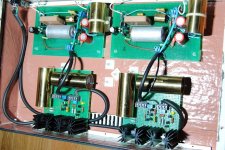
Moving the shunts inside the case did not help... so I decided to shield power from shunts to riaa boards.
Used the same Klotz mic cable as before and connected the shiels to star gnd only on the shunt side.
Now hum is so low that can be ignored.
🙂
Used the same Klotz mic cable as before and connected the shiels to star gnd only on the shunt side.
Now hum is so low that can be ignored.
🙂
Hi,I decided to shield power from shunts to riaa boards.
what was the arrangement of the power cable?
What are it's terminations like?
How does power run through the RIAA PCB from the power cable termination?
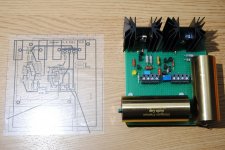
Power comes from outboard psu into a 5 pin XLR.
Inside riaa case, power goes from XLR to the shunt using 2 core shielded cable. Shield is used to connect shunt to star gnd at XLR. Two inner wires carry (+) and (-).
From shunt to riaa board I use two cables:
Sense (+) and (-) are connected using single thin coax.
Force (+) and (-) connected using the same mic cable as before.
Remenber that I had no problem with my previous v1 shunt.
Attachments
What about this:

Using your HV & LV shunt regulators to power it?
Wich Tx voltages & currents?
P.S. Sorry for off topic.
Last edited:
- Home
- Source & Line
- Analogue Source
- Simplistic NJFET RIAA