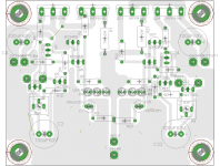
PCB Layout
See any major design flaws in this layout. This is the Shunt regulator. I put both regs on the same board. It will be fed by a very stiff comon power supply.
The power supply will produce 51V using a RCLC filter. PSUDII calculates ripple at under 200uV.
The RIAA circut will be 1 board per channel. Still working on that layout
Attachments
Its like with BJT and JFET input op amps if you got some experiences with such. I personally feel better with a simple channel, although BJTs are easier to hit better NF-Source Resistance in the lows using less paralleled.
Salas
Linear has FET duals as well, see attached LS3945.
Regarding differntial stages... I mean the version with the grounded base or gate of the non-inverting transistor. Output is the inverted stage with a buffer as emitter- or source follower.
My first impressions are that the higher frequency and the bass is more accurate. Just the experiments and I'd like to know your impressions.
Attachments
Are you using a Tango EQ-600P LCR or something similar ?
This will build up the final cost... do you believe it is better than the actual RC circuit ?
Caro Ricardo
I have a Tango and the version from Netherlands supplier "Acoustic Dimension" on hand but I'm building my own in future.
Is it better, yes or no? A worse LCR-RIAA will be beaten by a good made RC-RIAA - build with Cadddock MP132 resistors and matches caps. An LCR-RIAA is the cream, and for me I will use it as standard in my designs.
See any major design flaws in this layout. This is the Shunt regulator. I put both regs on the same board. It will be fed by a very stiff comon power supply.
The power supply will produce 51V using a RCLC filter. PSUDII calculates ripple at under 200uV.
The RIAA circut will be 1 board per channel. Still working on that layout
R22 too far. In general gate stoppers better be very near to gates. I would prefer defined ground lines to a ground area also. This reg is very difficult not to work in any layout though. Better make 2 exactly same ones on the common board, but having own grounds, with ability to wire two different rectified DC inputs for when you may have a second transformer for full double mono. You can use a couple of jumpers for common feed as for now.
Salas
Linear has FET duals as well, see attached LS3945.
Regarding differntial stages... I mean the version with the grounded base or gate of the non-inverting transistor. Output is the inverted stage with a buffer as emitter- or source follower.
My first impressions are that the higher frequency and the bass is more accurate. Just the experiments and I'd like to know your impressions.
I think that the better freq extremes are due to the buffer. If you try the higher current doubled up Jfet like SGreg's or Franz's they are more dynamic and maybe you can skip the buffer. Less stages. En=10nVsqrtHz for the LS...0.95 for 2SK170.
I don't know where you found your data.En=10nVsqrtHz for the LS...0.95 for 2SK170.
Toshiba say 0.95nV/rtHz @ 10Vds, 1mA & 1kHz for the 2sk170
Linear say 0.9nV/rtHz @ 10Vds, 2mA & 1kHz for the lsk170
Last edited:
Hi Salas
Just found this VAN DAMME - 268020 - CABLE VAN DAMME|268020|CABLE, MICROPHONE, BLACK, PER | Farnell Portugal
Can I use it for shielded power lines between psu and shunts ? I am not sure because the conductors are 24AWG only.
Regards
Ricardo
Just found this VAN DAMME - 268020 - CABLE VAN DAMME|268020|CABLE, MICROPHONE, BLACK, PER | Farnell Portugal
Can I use it for shielded power lines between psu and shunts ? I am not sure because the conductors are 24AWG only.
Regards
Ricardo
Hi Salas
Just found this VAN DAMME - 268020 - CABLE VAN DAMME|268020|CABLE, MICROPHONE, BLACK, PER | Farnell Portugal
Can I use it for shielded power lines between psu and shunts ? I am not sure because the conductors are 24AWG only.
Regards
Ricardo
Hi Ricardo,
I am using 24AWG silver plated teflon between PSU & shunt regulators with good succes.
Best
Felipe
Thanks Salas, will make changes as suggested. Including making it more of a star ground.
Very late to the party. Is this for an eventual group buy?
Better late than never. Never really intended it for a group buy, more along the line of the challenge of learning something new.
P.S. In reality I have over 1400 albums stored that I can't play. So in many ways a have a pretty good start;-)
P.S. In reality I have over 1400 albums stored that I can't play. So in many ways a have a pretty good start;-)
I think that the better freq extremes are due to the buffer. If you try the higher current doubled up Jfet like SGreg's or Franz's they are more dynamic and maybe you can skip the buffer. Less stages. En=10nVsqrtHz for the LS...0.95 for 2SK170.
Thanks for the suggestions ... I like to use low impedance circuits and for this reason I use the buffer stage. SK170 current is around 3mA and the buffer's current is 35mA.
I tried the single SK170 with current up to 7mA but the sound with the buffer is more open and relaxed.
Or do I misunderstand you, is your suggestion to use a paralleled SK170 as voltage amplifier - drain is the output - for the outputstage and high current? What's your output impedance?
Otherwise less stages aren't the better way in general. The combination of the voltage- and output transistor you can define as 1 stage.
Joao, What variant of the sk170 are you using? GR= 3-7 BL = 6-12, and V= 10-?. I was curios, if I could find the V variant it may eliminate the need for a buffer all together and still have a reasoably low impedance.
Found a KLOTZ MY206 mic cable in a local guitar store.
I will now wire tha PSU -> Shunt lines with it.
This cable has two inner cores and an external copper mesh. I will transport (+) and (-) with the inner cores and connect the outer screen to star GND (only on one side).
Hope this eliminates the slight hum I am having 🙂
I will now wire tha PSU -> Shunt lines with it.
This cable has two inner cores and an external copper mesh. I will transport (+) and (-) with the inner cores and connect the outer screen to star GND (only on one side).
Hope this eliminates the slight hum I am having 🙂
Salas
Regarding differntial stages... I mean the version with the grounded base or gate of the non-inverting transistor. Output is the inverted stage with a buffer as emitter- or source follower.
Here is what I was commenting. I thought you said using a buffer after first stage too.
Found a KLOTZ MY206 mic cable in a local guitar store.
I will now wire tha PSU -> Shunt lines with it.
This cable has two inner cores and an external copper mesh. I will transport (+) and (-) with the inner cores and connect the outer screen to star GND (only on one side).
Hope this eliminates the slight hum I am having 🙂
If its not a tiny ground loop somewhere, and its some little field, it will.
Well, the GND layout is the same as before and I did not have any hum with the v1.
With the v12 fullfilm I hear a slight hum when at full power and no signal in.
I guess the big caps are picking up from the nearby psu lines.
I believe it is a field because the hum is greatly reduced just by closing the riaa case lid 🙂
With the v12 fullfilm I hear a slight hum when at full power and no signal in.
I guess the big caps are picking up from the nearby psu lines.
I believe it is a field because the hum is greatly reduced just by closing the riaa case lid 🙂
Otherwise less stages aren't the better way in general. The combination of the voltage- and output transistor you can define as 1 stage.
A buffer although sometimes beneficial, I use it in the simplistic too, its a stage on its own utilizing 100% local feedback in my eyes. Zo with the Jfet buffer here is around 40 Ohm. Else my DCB1 unity pre isn't a stage, its a glowing wire for connecting people's CDPs.🙂
- Home
- Source & Line
- Analogue Source
- Simplistic NJFET RIAA