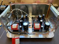
My C4 replacement is arrived and I swapped the damaged one. All is boxed. The only part that I’m still waiting for is my PSU front panel Voltage meter (not that is stopes me to start to listen to my phono). The one that I installed many years ago on that box is died. It was a cheap eBay item any way…. Please see attached images.
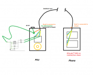
I made C2+C2Y test and ended up with 15.14nF (very accurately taken and via repeatable meter measured). Started with C2 alone and ended up my test roughly with 15. 6nF. Relatively hard to compare since it was sometime between swaps, but 15.14 gave me my full mental coherence and sensation of correct sound. C2 (14.89nF) alone as well as 15.6nF gave me some weird sensations and I felt for missing measures. As you know, all that is very subjective and might differ from person to person preferences, Also, it is related to system synergy in general. So, and as Salas indicated, the right tolerance for me is in-between 15.1nF and 15.2nF. My C2Y is combination of three of Mallroy polystyrene caps. You can see these on my images. Please also see wiring schematics attached.
It is very airy and more detailed sound. It is quite noticeable change compare to my classic Folded.
Attachments
-
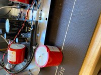 image0.jpeg851 KB · Views: 528
 -
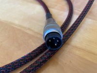 image9.jpeg646.9 KB · Views: 206
 -
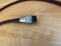 image8.jpeg746 KB · Views: 213
 -
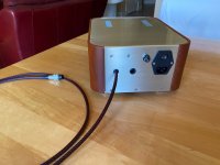 image7.jpeg609.2 KB · Views: 213
 -
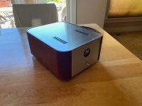 image6.jpeg482.1 KB · Views: 206
 -
 image5.jpeg693.3 KB · Views: 201
 -
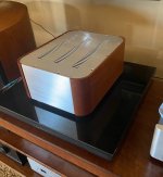 image4.jpeg476.8 KB · Views: 452
 -
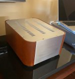 image3.jpeg355.4 KB · Views: 473
 -
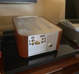 image2.jpeg541.4 KB · Views: 496
 -
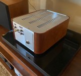 image1.jpeg535.3 KB · Views: 514

Beautiful! Grounding scheme shown is individualistic of course but it may also work for some.
Ummm.... Gorgeous build. Did you do all the wood/mill work? Fantastic.
I purchased four of these raw material boxes about 10 years ago. It was some guy from Canada who made these woodwork from cherrywood. All milling/drilling is mine. I polished and stained this raw wood with Danish oil also 10 years ago. Thanks for compliment.
Beautiful! Grounding scheme shown is individualistic of course but it may also work for some.
Thank you. Yes, and thanks for correction. It is only my way for GNDing. It might work for some and not for the others.
Some TTs ground best different than others indeed. BTW do you find this variation's sinking to floor choice better? Also the 1.3S PSU Vout drift logical for such a relatively high rail? I tried to improve on those practical things too given the all gains switchable redesign opportunity.
Some TTs ground best different than others indeed. BTW do you find this variation's sinking to floor choice better? Also the 1.3S PSU Vout drift logical for such a relatively high rail? I tried to improve on those practical things too given the all gains switchable redesign opportunity.
Yes, I do see that some TTs are use safety Earth connected directly to chassis (witch might set some Faraday) and tonearms are GNDed to it. Not in my case... My Wilson Benedch Circle One TT is connected to artificially made 120VAC with 90 deg shifted two sinuses. Body is made of some type of MDF. So, my tonearm with cart is totally floating for reference.
This is why I used suck GNDing way.
Floor sinking is very efficient method to dissipate heat from semi. We can use whole box as sink. No limitations for radiators sizes and etc. I see that as your genius design decision/choice. I used copper bar, but if guys uses 3mm bottom plate, then copper is probably not needed. I did not turned my unit off yet and I have about 34-36 deg Celsius on my bottom plate in average point.
I did not see any complexity (like huge swings) to set TP to 4V and drift was less dramatic than I remember from Classic Folded. I also like switches. Very flexible and accommodates variety of choices for all known needs.
Interestingly you ended up with C2+C2Y value alike the FSP average. Previous and new so far yet so close. Improvement not mutation. Did you hear any difference in bass and overall dynamics?
Hi — moving this question out of the GB to the general thread. In previously asking about calculating R8/R11 for higher IDSS than in the build guide, Salas provided the following helpful response:
“ To correctly use different enough K170 IDSS than noted in any NJFET Riaa thread's example schematic, unfortunately means special preparation trouble*. I prototype with frequent midway IDSS in my stash. That's to help sample chances for others. I have 200 Toshibas no more. When someone picks over and over for a particular narrow bracket of IDSS it's going to eventually deplete though.
*Breadboard the whole section from R7 and beyond. Including R7 but not C4. Substitute R8 with a hundred Ohm rheostat and R11 with a 5k rheostat. B+ should be 34V. Then adjust them rheostats to drop 25V across R10 and 14V across R11. Measure the trim values and use resistors closest to those values in the final assembly along with the same Q4 Q5 Q6 in same positions. Q5 Q6 shouldn't differ more than 1mA between them in the first place, always using the stronger of the two as Q6. All three should not differ to the other channel's K170s.
Q1 Q2 have an IDSS/Rs (R2 R3) look up table of recommendations in the FSP guide and they will work for MC. Beyond 12.5mA IDSS you got to make sure you can still find T.P 4V when with the example R19 R20 values and a logical B+ range for HMC and MM in UFSP.”
For the lazier among us, would it be effective to socket R8/R11 and measure the corresponding voltage drops? I have purchased all the combinations listed in the BOM for the K170 resistor values. I don’t have any reason to question the IDSS measurements on my K170s, but the proof I guess will be in observing how they behave in the actual circuit.
Thanks
I did most of this work for this.
see the following tabs on the spreadsheet
UltraFSP BOM - Google Sheets
2SK369 resistors, 2SK170BL resistor tabs.
I tested a bunch of different values to expand use of wider range of IDSS than the original build guide suggested.
Alex,what kind of caps have you in your folded simplistic? congrats for the wonderful ufsp you made!My C4 replacement is arrived and I swapped the damaged one. All is boxed. The only part that I’m still waiting for is my PSU front panel Voltage meter (not that is stopes me to start to listen to my phono). The one that I installed many years ago on that box is died. It was a cheap eBay item any way…. Please see attached images.
I made C2+C2Y test and ended up with 15.14nF (very accurately taken and via repeatable meter measured). Started with C2 alone and ended up my test roughly with 15. 6nF. Relatively hard to compare since it was sometime between swaps, but 15.14 gave me my full mental coherence and sensation of correct sound. C2 (14.89nF) alone as well as 15.6nF gave me some weird sensations and I felt for missing measures. As you know, all that is very subjective and might differ from person to person preferences, Also, it is related to system synergy in general. So, and as Salas indicated, the right tolerance for me is in-between 15.1nF and 15.2nF. My C2Y is combination of three of Mallroy polystyrene caps. You can see these on my images. Please also see wiring schematics attached.
It is very airy and more detailed sound. It is quite noticeable change compare to my classic Folded.
Alex,what kind of caps have you in your folded simplistic? congrats for the wonderful ufsp you made!
I used ClarityCap MRs, Mundorf’s EVO Al Oil, and Vishay’s.


Last edited:
I did most of this work for this.
see the following tabs on the spreadsheet
UltraFSP BOM - Google Sheets
2SK369 resistors, 2SK170BL resistor tabs.
I tested a bunch of different values to expand use of wider range of IDSS than the original build guide suggested.
Thanks, yes -- I have purchased the resistors corresponding to my measured IDSS as included in your BOM (THANKS!), as well as most of the other combos just in case something is off. I guess what I was trying to say is that I have confidence that I measured the JFETs accurately, but I also feel like I'll only really know once they are in the circuit..
I used ClarityCap MRs, Mundorf’s EVO Al Oil, and Vishay’s.
View attachment 855487
View attachment 855488
0.47uF C3 you had in your previous maybe explains some rumble. It was in the directions you could choose between 0.047uF to 0.1uF.
Raw PS
I know this whole thing has been really well thought out and and I am not qualified to second guess so I'll just ask the question. Is there any benefit to feeding the UBib's with separate transformers. I guess that would be separate raw power supplies.
Thanks, Don
I know this whole thing has been really well thought out and and I am not qualified to second guess so I'll just ask the question. Is there any benefit to feeding the UBib's with separate transformers. I guess that would be separate raw power supplies.
Thanks, Don
I know this whole thing has been really well thought out and and I am not qualified to second guess so I'll just ask the question. Is there any benefit to feeding the UBib's with separate transformers. I guess that would be separate raw power supplies.
Thanks, Don
you do not need separate RAW supplies. It's a dual mono supply.
You could use a 15+15 transformer is series, or two 32+32 and just wind the primaries together (same color wires).
It may improve the soundstage over using one transformer. Most of my listening tests were done with two.

It's two independent 30-32V secondaries. Can be obtained from off the shelf or made to order transformers. Usually you find 15+15V units to wire in series for 30V each. Going double mono. You can also find a 32+32V unit to use one secondary per raw supply (shared core) or buy two such units and parallel their secondaries per unit. Ending up with 32V double mono. Which is the most plentiful of all options.
- Home
- Source & Line
- Analogue Source
- Simplistic NJFET RIAA