Thanks for the info Salas,
I'd add to the changes (just to sum it up) the variation of R8 and R11 according to the Idss of Q4 and Q5.
I might have to change those (resistors) too. I have plenty of time till the board arrives.
One more thing: now we lost the F, it's not folded any more, UltraSP
Its as folded cascode as the previous only in ultra package revision because of new conveniences and ultrabib supply
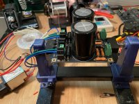
Moving along nicely here -- finished the Raw PSU. Using AS-0532 transformer, unloaded AC in @ 33.8v; unloaded DC out @ 45.6v.
Will move onto the main boards now that I have all the parts in hand.
I am working on some CAD files for drilled separate Modushop Galaxy chassis for the raw PSU and the main boards. I'll share them when finished.
Will move onto the main boards now that I have all the parts in hand.
I am working on some CAD files for drilled separate Modushop Galaxy chassis for the raw PSU and the main boards. I'll share them when finished.
Attachments
I now have the build complete and rebiased in the box. I have never tweaked the loading resistor before on my previous phono stage, is there a guideline or do I just try different settings and let my ears be the judge? Any other advice? Also can you switch the loading live but with the volume down?
Cart is AT-OC5 with 0.4mv output
Pic of the old FSP boxed up courtesy of the lovely people at Modushop


Cart is AT-OC5 with 0.4mv output
Pic of the old FSP boxed up courtesy of the lovely people at Modushop
Great work.
The copper cap for C1 is also my preference. I would suggest to secure it in a way that the leads are shorter. I've put the 0V wires beneath the pcbs.
The copper cap for C1 is also my preference. I would suggest to secure it in a way that the leads are shorter. I've put the 0V wires beneath the pcbs.
Just to be clear, I don't mean the specific caps but I do suggest having copper caps there.
Also be 0V wires I mean the ones the go from 0V to the chassis.
Also be 0V wires I mean the ones the go from 0V to the chassis.
Great work.
The copper cap for C1 is also my preference. I would suggest to secure it in a way that the leads are shorter. I've put the 0V wires beneath the pcbs.
Just curious why you prefer the copper Audyn. I have yet to order my big caps.
Thanks,
Don
in my fsp i prefer clarity cap,blue one,mr range in c1,but i have not heard copper cap there.
in my ufsp i am thinking using mundorf silver gold oil there.
in my ufsp i am thinking using mundorf silver gold oil there.
C1 is a 47nf or .047uf cap. are you talking about that or C3?
I find C3 most influential in both FSP and UFSP layouts.
I find C3 most influential in both FSP and UFSP layouts.
C1 is a 47nf or .047uf cap. are you talking about that or C3?
I find C3 most influential in both FSP and UFSP layouts.
yes,i meant c3.
Thanks for the comments. The 0v was not actually connected at that point, it is now and have been shortened and neatened up.
I picked copper because a friend recommended it. The leads are twisted and enamelled and do need shortening, you are right. However I am little worried about burning them off damaging the cap and it is a right fiddle to scrape them.
I picked copper because a friend recommended it. The leads are twisted and enamelled and do need shortening, you are right. However I am little worried about burning them off damaging the cap and it is a right fiddle to scrape them.
I now have the build complete and rebiased in the box. I have never tweaked the loading resistor before on my previous phono stage, is there a guideline or do I just try different settings and let my ears be the judge? Any other advice? Also can you switch the loading live but with the volume down?
Cart is AT-OC5 with 0.4mv output
Loading "damps" the cartridge's "electric generator" to various degrees. Play with its value until leading edge of notes and overall tonal balance seem best to you in your system. Certainly don't use less than ten times the value of the generator's coil resistance. If its not published, could be 10-12 Ohm for a 0.4mV AT. Thus start from no less than 100-120 Ohm load option. Not to depress its output much. You will literally hear the cartridge going louder with higher Ohm load steps. In many cases with such carts 200-220 Ohm sounds best in my experience. Open and dynamic enough before starting to sound hollow and treble oriented. But don't take that value to heart, its very much system synergy dependent.
You can switch loads live but with the volume all the way down when using this phono. It has the steady 47k R1 in parallel to the DIP load selections that always provides gate reference to ground for the 2SK369s. That way the circuit does not flap in the wind during switching input loads.
You are welcome. BTW we the people want to see final neat wired cutting42 FSP pic. Else we don't go to sleep. 😀
You are welcome. BTW we the people want to see final neat wired cutting42 FSP pic. Else we don't go to sleep. 😀
😀😀😀
Just curious why you prefer the copper Audyn. I have yet to order my big caps.
Thanks,
Don
My bad, I was referring to the smaller (47nf-100nf) caps. I find this phono in the neutral side with some setups might sound analytical so the fuller-sound of copper caps suits it better.
I prefer copper to aluminium in signal path in general but if I'm putting the last brush strokes in my whole system chain, I go for anything that sounds better to me.
@cutting42 I also see that Audyn Coppers are not in the same direction, one if facing the other way
Because the signal is quite low there might be an unwanted interference. Can say which way they should be looking because it depends on the cap. If you don't have oscilloscope you can ask the manufacturer or maybe someone here who has done the test
Good spot, not quite sure how that happened. Even for non polarity sensitive components I like to keep resistors etc all the same way round. Those slipped through, will fix before I get the running in started.
Thanks
Folks:
Apropos of very little, I wrote to Clarity Caps and asked which lead on their CMR series ran to the outer foil. Their response:
Just in case anyone was wondering...
Regards,
Scott
Apropos of very little, I wrote to Clarity Caps and asked which lead on their CMR series ran to the outer foil. Their response:
In reply to your email we write to advise the CMR caps are produced utilising a series film and therefore there would not be an outer turn as such.
Just in case anyone was wondering...
Regards,
Scott
- Home
- Source & Line
- Analogue Source
- Simplistic NJFET RIAA