Hi Joztom,
With your limited instrumentation, I can understand your comments. But many members have far newer 'scopes and meters than you do. In your hobby area, your analogue meter rules I guess. Not so in most hobbyist labs set up across the world.
Your meter is pretty good for general service, but I'm not sure it is good enough to set the bias current in audio equipment. You should have at least two decimal digits on the mV range. I don't know what your lowest DC voltage range is. The oscilloscope is a pretty solid unit, but you really need something newer as well. The spec-an depends on what you are doing, but from what you are saying I think you should have something that covers up to 30 ~ 40 MHz. An HP 3585A would suit, and a x10 probe for it. Careful with the input as it is limited to about 5 V pk as most spectrum analysers are. What do you use as an oscillator?
-Chris
Wanna bet? I know several people who have spectrum analysers. Look at other hobbies people pursue. Shooting costs thousands, fish, photography, astronomy, model railroads. It all depends on how interested you are and how much you might sacrifice for your hobby. Clearly many people will pursue this hobby with more determination than you will. That's not saying anything negative towards you, but you sure can't speak for many other folks out there. You should see how much can be sunk into precision time keeping and frequency references.Spectrum analyser cost a lot, it is not for DIY scene.
With your limited instrumentation, I can understand your comments. But many members have far newer 'scopes and meters than you do. In your hobby area, your analogue meter rules I guess. Not so in most hobbyist labs set up across the world.
Your meter is pretty good for general service, but I'm not sure it is good enough to set the bias current in audio equipment. You should have at least two decimal digits on the mV range. I don't know what your lowest DC voltage range is. The oscilloscope is a pretty solid unit, but you really need something newer as well. The spec-an depends on what you are doing, but from what you are saying I think you should have something that covers up to 30 ~ 40 MHz. An HP 3585A would suit, and a x10 probe for it. Careful with the input as it is limited to about 5 V pk as most spectrum analysers are. What do you use as an oscillator?
-Chris
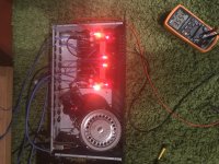
Due to a malfunction with my usual setup I decided to hookup one channel to my old lm3875. Just one channel as the other is missing a capacitor for some odd reason 😉 Anyhow.... whoa! Bloody ripper. Honestly I was not expecting such a difference. Even my wife noticed the improvement and that’s saying something. Looking forward to boxing everything up neatly, I can only imagine the potential. Again, thank you Salas, you’re a brilliant and generous person.
Attachments
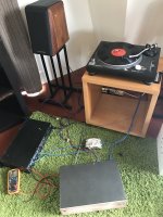
It’s taken me ages, bit by bit slowly. To be honest I nearly gave up this project because of life’s little turns. I’m so glad I stuck at it and got it running. A great feeling of accomplishment and it really does sound great. I’m going to keep working at this hobby, the joy I get when I hear the music play is priceless. 🙂 btw you really should build one Chris.
Due to a malfunction with my usual setup I decided to hookup one channel to my old lm3875. Just one channel as the other is missing a capacitor for some odd reason 😉 Anyhow.... whoa! Bloody ripper. Honestly I was not expecting such a difference. Even my wife noticed the improvement and that’s saying something. Looking forward to boxing everything up neatly, I can only imagine the potential. Again, thank you Salas, you’re a brilliant and generous person.
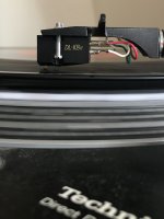
Nice. The other channel misses that reversed and cooked C8's replacement I guess. If the toroid in the picture isn't magnetically shielded it has the potential to throw some hum field on its nearby MC sensitive channel when it will be repaired and installed. Its not certain it will really intrude, but if it will, a copper or Mu metal band dressed around the trafo can help a lot in reducing its field. Nuvotem Talema :: Custom Design :: GOSS Band
*Many times just rotating the trafo for its secondary cables exit area to face most away from the sensitive electronics and their signal cabling gives a good improvement.
The JFETs for these aren't getting any easier to find (2SK369BL, 2SK170BL and 2SK117GR). You shouldn't wait too long, or obtain parts soon and hold until ready to build.
Finally got around to listening to mine today, using my son's Dual 721 w/Ortofon LM 30 cart (3mv MM). It sounded pretty good. I had never used this table before (still haven't dug mine out of storage). Gain appears to be quite sufficient.
There is still some hum at higher volumes, but I haven't redone the input wiring with coax yet.
A couple of questions:
There is still some hum at higher volumes, but I haven't redone the input wiring with coax yet.
A couple of questions:
- How does one measure the gain to check that both channels are the same or close?
- Is there any advantage or need to adjust the TP1-TP2 voltages to be equal between channels (this appears to be quite doable)?
1. Gen at 1kHz >100mV sine, voltage divider (with ~cart like impedance shunt part) down to 3-5mV, output measurement (AC RMS or scope pk-pk)
2. No
2. No
SUT or Optimized for Specific Cart?
......a general question directed for those who have built this phono. I have on order in the next group buy the NJFET kits from Tea-Bag and would like to start to plan my method of attack.
I have two different MC cartridges that I plan on using and DL103R (0.25 mV-14 ohms) and an AT33Sa (0.4mV-10 ohms). I also have on loan an Ortofon SPU Meister at 0.32mV- 2 Ohms.
To obtain the lowest noise ..... would it be better to assemble the NJFET RIAA as a MM stage plus very good SUT or should the NJFET be assembled with the particular MC in mind ?
I am particularly concerned about getting hiss or noise with a dedicated high gain version and am wondering what would be the easiest way to achieve the lowest noise. I am not adverse to buying a good SUT. I am planning to build the NJFET RIAA with a separate PSU box connected via umbilical.
I have built Salas' 6V6 pre-amp (high gain version) and will use that after the NJFET RIAA.
Thanks for your time.
Frank M
If its a balanced impedance SUT it adds the benefit of enough harmonic noise cancelling if the TT wiring is floating which is significant. That's about picking less hum and buzz. About hiss it will be about the same or bit better but not significantly different. Plus you can have MC & MM inputs to switch over if interested.
This is the perfect opening.
After installing a MM cartridge and taking my beloved SALAS phono stage to low gain I was immediately taken by what I would call a more relaxed performance. I do not think what I was hearing was due to solely to the cartridge.
My new cartridge, Saturday evening, lost its tip - just came off. Luckily this happened soon after purchase, which is the case more often than not for manufacturing defects.
So not being able to be without music I had to reinstall my back up cartridge, ZU 103. About two months ago my Transfiguration Proteus lost a coil after two years service. My previous Transfiguration had lasted for about twelve years and I changed because I wanted to hear what was now possible. That cartridge was still working and sounded good.
I had started with the high gain version because of these cartridges and I was very pleased with the sound.
I have done lots of power supply changes through the years and am now using something not recommended - a half wave rectified clclclcl filter for each channel - the regulators are bypassed. This supply is absurdly large but it makes it plain that regulators allow smaller supplies and can be very good but in my experience, in low level stages, (I have never used an amplifier with regulators so I have no idea what happens there) a BRUTE force supply simply sounds more like music and my phono is no noisier than it was before.
I think the half wave rectifier reduces noise. There has to be something to this since MARANTZ used half wave rectification in the 7 and there certainly was not a cost constraint there. Just to give some context ...
So I have a LUNDAHL LL1931 which I have not used in years. I installed this to be able to use the 103. Two 50K resistors in parallel with the 47K using 1:16 step up. I have no feelings about this transformer at all. It is the only MC step up I have so I have no way to compare it to anything. Many think the amorphous core sounds funny. It may but I do not hear it since I do not know what to listen for. Maybe it will appear before I return to the MM cartridge.
But my conclusion is the stage sounds better with a transformer.
I remember Herb Reichert talking about some tube, I think it was, and said it had a "jumpiness" to it. I took that to mean a restlessness which implies some kind of instability. That is what I think i am hearing. With all due respect to Salas who has given us this circuit my feeling is like that old line about just because you can do something doesn't mean you should.
I am only speaking for LOW output moving coils, of course. i am speaking of the parallel 2SK369 version.
It needs to be added I am fully aware something could be wrong with MY phono stage. I do think both channels sound alike, both before and after. I did have problems with initial assembly and got some incredibly generous help from TEABAG. I could very well have overheated the 369s and that made them more variable in high gain mode.
Starting out with high gain before one can afford a step up for your favorite cartridge is something to consider.
As far as the moving magnet I have been very pleased with the sound. You do not get the spatial effects even a 103 can deliver. In contrast I am hearing a much greater sense of timbral detail. Instruments have more character. Phrasing is more detailed. I might be happy with this for the rest of my listening life.
Note about the Proteus. Shortly before my cartridge failed the fellow who is Transfiguration died so I may never hear that cartridge again. I thought this cartridge would have been my mainstay for another ten years. Oh, well ...
If less "jumpiness" is about a less "boiling" background with LMC, then its the gain in harmonic noise reduction achieved by a balanced impedance input i.e. the trafo's common mode noise cancellation ability when fed from a floating TT wiring (all the way).
Marantz 7 uses a full wave rectifier
Nope, the Marantz 7 uses a full wave rectifier. The center tap is grounded, so only two diodes are required to achieve full wave rectification.
Rush
This is the perfect opening.
I think the half wave rectifier reduces noise. There has to be something to this since MARANTZ used half wave rectification in the 7 and there certainly was not a cost constraint there. Just to give some context ...
Nope, the Marantz 7 uses a full wave rectifier. The center tap is grounded, so only two diodes are required to achieve full wave rectification.
Rush
Attachments
Yup, no designer would live with half wave rectification it the option for full wave is available!
-Chris
-Chris
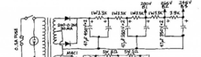
That is not the schematic for the Marantz 7, that is somebody's drawing of what they would recommend to mess the thing up.
I found it at PRESERVATION SOUND and he very clearly states he has changed the supply to the conventional wisdom of full wave rectification.
There is not a schematic of the power supply in the service manual.
I can assure you the B+ supply for the tubes used a half wave rectifier and there had to be a reason for it. They certainly did not "skimp" on the cost of a rectifier.
Why is left to those with the curiosity to find out for themselves.
Nice progress up to now 
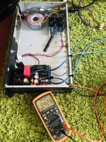
Hey, you can FFT the output on your Keysight scope and look for the 50Hz hum band and its higher harmonics. Then watch them going down or up when manipulating the build for grounding scheme, rotating or shielding with a flux-band or moving the trafo away etc. Is the pcbs ground also connected to the chassis as it should? The Y cables should attach to the chassis too. Lift one lead from just one of those two 1 Ohm resistors in the air. Is there any change in the little hum? You can even Bode plot the RIAA curve with that scope! (Maybe it takes a 1:100 two resistors divider 1k series 10R shunt to feed the phono for better SNR from the scope's gen or not)
Hey, you can FFT the output on your Keysight scope and look for the 50Hz hum band and its higher harmonics. Then watch them going down or up when manipulating the build for grounding scheme, rotating or shielding with a flux-band or moving the trafo away etc. Is the pcbs ground also connected to the chassis as it should? The Y cables should attach to the chassis too. Lift one lead from just one of those two 1 Ohm resistors in the air. Is there any change in the little hum? You can even Bode plot the RIAA curve with that scope! (Maybe it takes a 1:100 two resistors divider 1k series 10R shunt to feed the phono for better SNR from the scope's gen or not)
- Home
- Source & Line
- Analogue Source
- Simplistic NJFET RIAA