I’ve binned the old cap, it was definitely faulty, slight bulge and I could feel it heating up under the PCB
Wasn't put in wrong polarity for sure?
Your scope has frequency response plotting. Maybe you could make it graph the RIAA curve. Tiny signals in this case though. Normal gens aren't super low noise for such. Maybe through a 1k to 10Ω Lpad so to drive 100mV for 1mV output. The gen's signal to can strongly rise above its residual noise that is to be divided by the ratio of hundred as well.
Sorry, lpad? I’m not sure what it is. Are you saying the gen will be noisy at 1 mv.
Last edited:
With FFT for all signals and response plotting for onboard gen sync, a responsive scope like your Keysight 1000x can basically confirm all is well for circa 60dB dynamic range. Its not an Audio Precision station for characterizing spec in development but it can practically tell you, hey mister your build is a pass with no obvious trouble. Who would have expected in the old days of an eponymous scope with really useful analyzer extensions and a 20 Meg gen in one little box for 600-700 US$. Even ten years ago it was unthinkable!
Sorry, lpad? I’m not sure what it is. Are you saying the gen will be noisy at 1 mv.
https://www.electronics-tutorials.ws/attenuators/l-pad-attenuator.html
My SDG2042X Siglent gen is one of the cleanest economic gens and I wouldn't consider it pristine at so low output levels. I always use a voltage divider for testing phonos. Especially when using ARTA etc. See the FSP's true noise (LMC mode) here in non averaged grass. To do such 24bit graphs without external interference I have the divider's resistors shielded in a copper tube with female RCA in at the back and a male RCA out at the front. The audio interface's signal passes through to enter the phono after a strong division. The audio card has much supersonic noise. Must be divided. Economic scopes are 8 bit BTW. But they enhance the basic ADC's 8 bit 50dB SNR with their memory oversampling in FFT.
Attachments
Amazing piece of kit for the money alright, very flash for a beginner like myself.
I’ve got a long way to go and lots to learn.
Oops you already answered my question while I was typing
I’ve got a long way to go and lots to learn.
Is this a jig that you feed a 100mv signal into that puts out 1mv?Maybe through a 1k to 10Ω Lpad so to drive 100mV for 1mV output.
Oops you already answered my question while I was typing
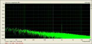
In that graph above I fed 1/4 mV to the LMC mode FSP (62dB gain setting). I used 1/200 division to have a usefully steady 50mV original signal from the audio card. If I asked for such a tiny 0.25mV signal straight out from any gen or interface it wouldn't even bother to be produced not to mention chances of making it through the interference pass its output BNC socket if it dared be produced 😀
Ok then, wow! Sensitive stuff. So are the wires coming from the cartridge to the FSP super sensitive to external noise at LMC setting also?
Ok then, wow! Sensitive stuff. So are the wires coming from the cartridge to the FSP super sensitive to external noise at LMC setting also?
Yes, if you will near a mains cable to them they should pick hum no matter they are shielded. If you have the system's wiring well dressed, no transformers and AC cabling near inputs and outputs or near the TT and the main phono box, you will have a chance of non "boiling" at idle vinyl source. Given the grounding scheme will be a success. 62dB is 1259 times voltage gain!!! Imagine examining a fabric under such a magnification microscope and not finding bothersome picked up dirt. Its no mean feat we manage to make an LMC cart's signal amplified and reverse equalized up to line level while keeping it satisfactorily dirt free.
BTW the cartridge isn't a digital gen to struggle synthesize a very small signal through limited bits and electronics self noise, its little mechanical signal generator maybe tiny in output but almost self noise free. Interference is the enemy alone.
Great information thank you🙂 Definitely gonna build an Lpad and give it ago with the FSP. I’m thinking Lpads would be good for experimenting with small signal amplifier design, preamps etc also I guess. Breadboard experiments. Also reducing large output voltage from power amps.... 🙂
Last edited:
They also pick up noise by increasing the impedance though. Lab experiments are a whole world of traps and workarounds, you will see. Very educating and worthwhile though. Start with line level experiments on a receiver or something. Or with a not too fast op-amp on a breadboard set for moderate gain. For the signal to be robust enough and flat in response so to build your first skills on the new scope easier. Keysight scopes have extensive guide and explanations when pushing the help button while measuring.
Wasn't put in wrong polarity for sure?
For sure! Hmmm sure
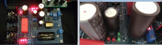
It was populated in wrong polarity after all. That was the cause of your troubles, not an intrinsically bad cap. Check the negative orientation stripes on C8 capacitors in the combined picture attached. Contrasting a picture saved from my prototype build vs yours while debugging.
Attachments
🙄🙄 Did I do that? Never! 😀 So the leds we’re slowly frying it.
Well done Mr Holmes and my apologies for bringing Mr T into my muddle up.
Well done Mr Holmes and my apologies for bringing Mr T into my muddle up.
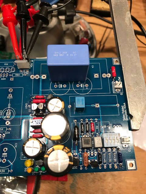
Working on mine, and finally got the rest of my parts to start testing. Board #1 came right up, no adjustment required, running at 35V using a bench PSU. TP1-TP2 was at 3.45V, very stable, though I didn't leave it on too long.
I'm planning on powering these with one or two GRLV plus regs set for 35V, goldenreference low voltage power supply - Do It Yourself - www.Head-Case.org
I tried to use parts I had around (Holco 47K for R1/R14, PRPs and Dale RN60s). Ordered some Vishay PTF and Welwyn RC55s for some other spots and will probably replace some/most of the others with RC55s. Goal was to use the lowest ppm resistors possible without paying $$$ 🙂 Cartridge is an AT ML440mla; these are configured for 40dB right now, loading will be 32K.
These are some boards I had run myself. They do have the Salas shunts on them, not populated. I'll try them this way first, but may populate and use the shunt regs later. The GRLVs are very low noise (~800pV in a screen room).
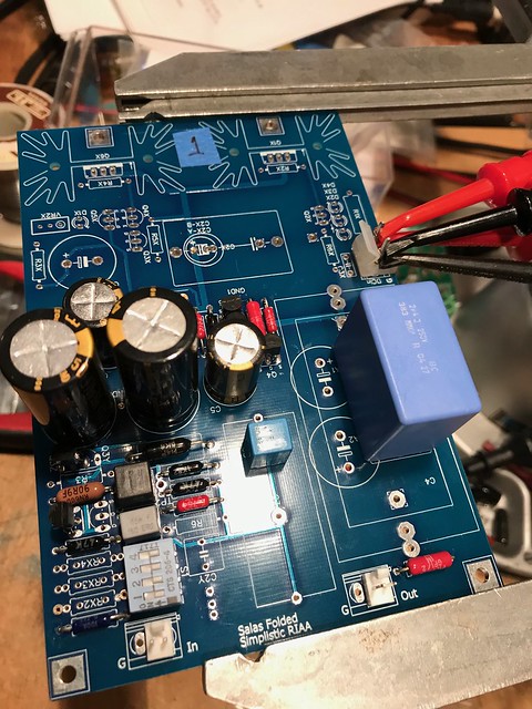
The 2nd board came right up as well, TP1-TP2 was 3.65 or so on that one without adjusting anything. TP-1 to ground was 7.76V on the 1st board, and 7.73 on the 2nd, which should be the voltage across the 4 LED string, so about the same as what I measured when I matched these. I did heed your advice and use the 2SK117 (Q7) and a 3.3K resistor with a bench PSU and did the whole string instead of measuring individual LEDs.
I wanted to ask; I used Nichicon KZ caps as I had been told that the newer Elna Silmic IIs aren't as good (Wayne from Pass Labs said he had quit using them). I see from pictures that a lot of people seem to use them.
I also bought some Panasonic FRs, but the lead spacing is smaller than the foo foo caps are, so not sure how well they would fit. 🙂 Big plus in the 105*C rating and 10,000 hour life vs. the 85*C / 1000 hours of the KZs and probably similar in the Elnas. The brown wrapper on the Elnas is IMHO fugly as well, but didn't consciously enter into my decision.
Hi Nick, when i tested my FSP with generator and L pad to see the frequency responce I did use Sinusoidal waveform of course. For a moment I use Square and sawtooth for fun, and I realize that those are "converted" to Sinusoidal to the output, specialy square. Is that ok or because of charging of the serial capacitors or i have to worry about?
- Home
- Source & Line
- Analogue Source
- Simplistic NJFET RIAA