With changes to their associated resistors values per specific IDSS yes. Just by dropping in V as those values are now, no.Dear Salas,
There are lots of 2SK170Vs finding their way into the market - could these be useful for Qs 4/5/6?
Take care,
1. R4, R15. Can I use slightly higher values (2K21, 3K32) for low MC build?
2. Could it be beneficial or detrimental for the PSU filtering to install 10 000 uF caps (have them already) at RAW PSU and then 4700 uF near phono pcb after the umbilical?
3. Regulator C2X. How and when it's worth to place EVO there?
Thank you.
2. Could it be beneficial or detrimental for the PSU filtering to install 10 000 uF caps (have them already) at RAW PSU and then 4700 uF near phono pcb after the umbilical?
3. Regulator C2X. How and when it's worth to place EVO there?
Thank you.
1. Yes
2. Doable. I don't know if it can make an audible improvement. But its not electrically detrimental.
3. Few previous builders who used it there, praised it. I don't have personal experience of it there.
2. Doable. I don't know if it can make an audible improvement. But its not electrically detrimental.
3. Few previous builders who used it there, praised it. I don't have personal experience of it there.
Just to confirm what I have found out somewhere, sometime in the thread:
if I have a precise R6 from Tea-Bag, can I ommit it shunting R5?
if I have a precise R6 from Tea-Bag, can I ommit it shunting R5?
R5 & R6 are two parallel resistor positions. R5 is the basic 6.8k and R6 1Meg trims R5 down a little. When having the precise 6.75k very low ppm custom value of Tea's kit you skip R6.
What do you guys about those Schurter type in line filters? They are quite more expensive vs simple power entry models. Effective enough?
Also, I would like some help reading those graphs. Do I understand correctly, lower current models provide better filtering?
Also, I would like some help reading those graphs. Do I understand correctly, lower current models provide better filtering?
Attachments
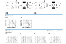
All the data I have seen shows the higher current models havingless effective interference attenuation.
It's probably due to the higher current common mode inductor having fewer thicker turns giving less impedance.
Don't use the "Medical" version shown on the right, unless you have a medical specified piece of equipment that requires it.
It's probably due to the higher current common mode inductor having fewer thicker turns giving less impedance.
Don't use the "Medical" version shown on the right, unless you have a medical specified piece of equipment that requires it.
Thank you, Andrew. How do I calulate what's the lowest current model possible knowing that FSP draws about 100mA per channel. My guess it's 1A. But I don't want to guess each time.
1A from a 220Vac mains is equivalent to 220W. That's a lot of power for a domestic system replaying music audio.
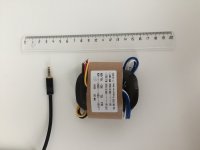
R-Cores from Asia arrived.
They looks suspiciously small.
Or I think they look smaller than my previously owned 30VA R-Core.
I might be wrong.
Including a pic with a headphone jack as a reference.
Is there a way to test them if they are specified correctly and well made in general?
They looks suspiciously small.
Or I think they look smaller than my previously owned 30VA R-Core.
I might be wrong.
Including a pic with a headphone jack as a reference.
Is there a way to test them if they are specified correctly and well made in general?
Attachments
R-Cores from Asia arrived.
They looks suspiciously small.
Or I think they look smaller than my previously owned 30VA R-Core.
I might be wrong.
Including a pic with a headphone jack as a reference.
Is there a way to test them if they are specified correctly and well made in general?
Would you care to share your source ?
R-Cores from Asia arrived.
They looks suspiciously small.
Or I think they look smaller than my previously owned 30VA R-Core.
I might be wrong.
Including a pic with a headphone jack as a reference.
Is there a way to test them if they are specified correctly and well made in general?
That certainly is compact. I see the transformer has two secondary windings, each rated to deliver 18V at 830mA (14.94VA). You will need to connect them in series.
Start by measuring the output voltage of the combined series secondaries unloaded. Also measure the mains voltage on the primary (VERY CAREFULLY!). Now lightly load the secondaries, say about 4K Ohms resistance to draw about 10mA, record the voltage. A one Watt resistor should be OK, but as you draw more current the load will dissipate more power, so you will either need more resistors in parallel or higher power resistors. So now draw about 50mA and see what happens to the voltage. Then 100mA, then 200, etc. Monitor the temperature of the transformer as you draw more current. Watch the temperature of the load resistors too, you don't want to start a fire! You don't need to go beyond about 400mA total to get a good picture of the transformer's regulation.
Remember the FSP only draws around 100mA per channel, and it uses a shunt regulator with a constant current source, so the load seen by the transformer is constant and independent of signal or load on the output of the preamp. If you can draw 100mA (roughly 400R load, you will need at least a 5W resistor or parallel a few higher value resistors of a lower power rating) and the secondary voltage stays near 36V (for some value of "near") and the transformer doesn't get hot, you are good to go. I would also test at around 200mA, just because.
Found a 30VA 9+9V R-core at home with the same sticker.
Same size. A little bit relieved.
Bought in this Chinese shop.
But it was shipped from Singapore.
Poor comms in general.
Payed 53$ total for two 30VA transformers.
Arrived with DHL in 11 days.
Could have been even faster, but because of some asian holidays and address mistype it had 4-5 days delay.
Same size. A little bit relieved.
Bought in this Chinese shop.
But it was shipped from Singapore.
Poor comms in general.
Payed 53$ total for two 30VA transformers.
Arrived with DHL in 11 days.
Could have been even faster, but because of some asian holidays and address mistype it had 4-5 days delay.
I've measured the 2SK117GR for Q7, Q2x, Q3x and Q5x but they're all measuring high, between 8.1mA and 11.2mA. The target for Q7 is 4-5mm and 3-4mA for the others. Is this a problem?
Should I use the lowest 8 (8.1mA to 9.8mA)? Do I need to tweak any resistors maybe?
Apologies if this has been asked before - it's a long thread and I didn't find anything searching.
Should I use the lowest 8 (8.1mA to 9.8mA)? Do I need to tweak any resistors maybe?
Apologies if this has been asked before - it's a long thread and I didn't find anything searching.
No K117GR should measure >6.5mA IDSS as by TOSHIBA spec. They are fake parts. Don't use them at all.
Hmmm, okay thanks chaps. Mine came from Tea, as no one else has had similar problems I'd better remeasure them.
Hmmm, okay thanks chaps. Mine came from Tea, as no one else has had similar problems I'd better remeasure them.
The stash I use I have been using for over a year. Although the usually run more in the 4-6ma range typically, I have never seen one hit 7ma.
This is the setup I use, but at 10V typically.


- Home
- Source & Line
- Analogue Source
- Simplistic NJFET RIAA