I am going to start the build on the Salas Folded has any one (Riccardo for sure 😀 ) made the exact calculations for the RIAA components?
Could you please post them again OR maybe the formulae
Tanks
Could you please post them again OR maybe the formulae
Tanks
Hi Bksabath
Please post here the values of the components you are going to use and I will be glad to do a sim for you 🙂
Please post here the values of the components you are going to use and I will be glad to do a sim for you 🙂
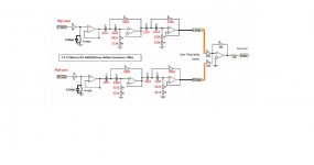
I wrote several articles about passive vs. active filters (design and performance) and I made my decision to build Linkwitz “20Hz High Pass” with the integration into my Sub. It is easy since a lot of good quality of PCBs are on eBay. I'm going to put an input and also output buffer. Just for the reminder: it should help me to remove subsonic frequencies which are causing woofing-flipping effect on my subwoofer when I play records. No issue when I play CDs since CDs does not have that low-frequency data recorded. Please see attached schematics and PCB picture.
Attachments

One more aspect… I can hear perfect quality radio station when disconnect L-RCA TT output cable from input of my FSP and I hold RCA barrel it with my hand (it’s L-channel return).
Is it normal? If not and its RFI, then hot to treat that issue correctly?
Is it normal? If not and its RFI, then hot to treat that issue correctly?
I wrote several articles about passive vs. active filters (design and performance) and I made my decision to build Linkwitz “20Hz High Pass” with the integration into my Sub. It is easy since a lot of good quality of PCBs are on eBay. I'm going to put an input and also output buffer. Just for the reminder: it should help me to remove subsonic frequencies which are causing woofing-flipping effect on my subwoofer when I play records. No issue when I play CDs since CDs does not have that low-frequency data recorded. Please see attached schematics and PCB picture.
That is a 4-th order LR with unity gain buffers on in and out so you dont need anything more then that.
That is a 4-th order LR with unity gain buffers on in and out so you dont need anything more then that.
Yes it is. This why I choose it.
It is a kit on eBay and I slightly modified it for my needs.
New 2 1 24nu llO ctSter eoActi veCrossov erSing leS ubOutp utButtkick erP | eBay
do you realise that you have used 4 extra opamps? Compared to:................I made my decision to build Linkwitz “20Hz High Pass” with the integration into my Sub. ............... Please see attached schematics and PCB picture.
Input summer opamp>>first 2poleHP>>second 2pole HP. equals 3 opamps for the same 4pole HP filter with a low impedance output to feed the next stage.
Last edited:
Hi Bksabath
Please post here the values of the components you are going to use and I will be glad to do a sim for you 🙂
I am going to use the values on SCH and as I have same RC55Y left I may be using those whit the E96 table values Resistor Tables | Electronics and Electrical Engineering Tools | EEWeb Community
R14 = 47.5 K and R5 = 6.81 K
It is very kind of you to sim those values for me
I was asking for the calculated values as I rather match the values on the smaller side for example use 6.65 K instead and maybe play whit the capacitors as it is much easier to match those by adding same small values ones in parralel
I wrote several articles about passive vs. active filters (design and performance) and I made my decision to build Linkwitz “20Hz High Pass” with the integration into my Sub.QUOTE]
Don't get me wrong I like the discussion about cross over so please do carry on but why one is going to put 3 integrated circuit in the signal pat when all scope of folded / simplistic is to keep things simple?
+ you sure that 20 Hz -3db frequency is right
Why not a 18 db cebicew (or sumthink like that) at 13 Hz or better 7Hz
Why not move TT to a better place? maybe like me U have a floating floor and only way out is to fit a shelf to the wall.
I had the simplistic running whit F5 Polk LSi15 at punch in the tummy level and 3D staging of simplistic was mind boggling so good why risking to compromise that
20Hz killer IMO is worst proposition than a bit of cone flapping.
FURTHERMORE 😀
DO NOT IN ANY CIRCUMSTANCIES SAY THAT CD HAS BIT OF SIGNAL MISSINGWe do not want CD crowd here to start CD/ANALOG argument here ever again
One more aspect… I can hear perfect quality radio station when disconnect L-RCA TT output cable from input of my FSP and I hold RCA barrel it with my hand (it’s L-channel return).
Is it normal? If not and its RFI, then hot to treat that issue correctly?
You can create antenna in several ways, not that you have to try on purpose when a cart return is floating, one trick is to use 10nF C0G from RCA ring directly to chassis near it. That will ground early what RF can be gathered on the TT cable shield in normal connection. I would not recommend bandwidth limiting micro chokes in series with signal hot if there is no problem when normal connections in a particular build.
do you realise that you have used 4 extra opamps? Compared to:
Input summer opamp>>first 2poleHP>>second 2pole HP. equals 3 opamps for the same 4pole HP filter with a low impedance output to feed the next stage.
I did realize that I need an extra opamps vs. other types on HPs, but I have about 20 of OPA2134 in my home stock. They cost me 20c each and found them about year ago in local surplus store.
I wrote several articles about passive vs. active filters (design and performance) and I made my decision to build Linkwitz “20Hz High Pass” with the integration into my Sub.QUOTE]
Don't get me wrong I like the discussion about cross over so please do carry on but why one is going to put 3 integrated circuit in the signal pat when all scope of folded / simplistic is to keep things simple?
+ you sure that 20 Hz -3db frequency is right
Why not a 18 db cebicew (or sumthink like that) at 13 Hz or better 7Hz
Why not move TT to a better place? maybe like me U have a floating floor and only way out is to fit a shelf to the wall.
I had the simplistic running whit F5 Polk LSi15 at punch in the tummy level and 3D staging of simplistic was mind boggling so good why risking to compromise that
20Hz killer IMO is worst proposition than a bit of cone flapping.
FURTHERMORE 😀
DO NOT IN ANY CIRCUMSTANCIES SAY THAT CD HAS BIT OF SIGNAL MISSINGWe do not want CD crowd here to start CD/ANALOG argument here ever again
I’m sorry that I confused you. It is nothing to do with FSP. Please read my Post #14304 carefully. That filter will be integrated into my Sub and I’ll deal with the signal going to Sub, and Sub only.. All other components and signals will be untouched. I disagree about CD frequency range and it is not an issue of something actually missing there. CD has data recorder with 20Hz-20kHz range and this is why CDs doesn’t contain subsonic info below 20Hz.
Compact Disc Digital Audio - Wikipedia, the free encyclopedia
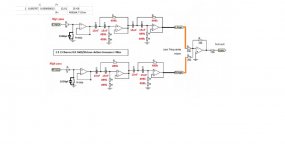
After final search of resistors and capacitors (MKP-1837, PTF56 and PTF 65) and came up with the final setup. I will have -6 at 15Hz. If that is OK -> I’ll see soon. I’m going to experiment now.
Attachments
You can create antenna in several ways, not that you have to try on purpose when a cart return is floating, one trick is to use 10nF C0G from RCA ring directly to chassis near it. That will ground early what RF can be gathered on the TT cable shield in normal connection. I would not recommend bandwidth limiting micro chokes in series with signal hot if there is no problem when normal connections in a particular build.
This is what I expected and I’ll try 10nF cap. However... how to connect cap to the enclosure near RCA? I’ll use RCA body latch to connect cap one leg, but I probably need to drill and thread back panel to connect its other leg. Do have any pictures of such thing, buy chance…?
I had used the TT ground lug leg once in a build that it was positioned next to the input RCA's. I don't think I have pictures. For best results the RF capacitors legs should be even shorter though. Maybe a very small screw and shallow thread between input RCAs on the inside wall for a tiny metal eyelet?
I had used the TT ground lug leg once in a build that it was positioned next to the input RCA's. I don't think I have pictures. For best results the RF capacitors legs should be even shorter though. Maybe a very small screw and shallow thread between input RCAs on the inside wall for a tiny metal eyelet?
I see. My TT GND lug in about 30mm away from Input RCAs. That will create 30mm leg, which I guess is too long. So, I’ll try to add some threads. Let’s see….
Is any other types of caps are good for that job beside C0G?
Long legs add inductance and that hinders the RF grounding efficiency. Whatever small body low loss film cap will also do.
Long legs add inductance and that hinders the RF grounding efficiency. Whatever small body low loss film cap will also do.
Got it. Thank you.
Don't U worry I am confused full stop
15Hz at -6db is ok but do not expect me to tell U what the -3db frequency is as abowe aplies.
Tanks for clarification about CD as I say we don't want Cd/Analog argument here.
15Hz at -6db is ok but do not expect me to tell U what the -3db frequency is as abowe aplies.
Tanks for clarification about CD as I say we don't want Cd/Analog argument here.
Long legs add inductance and that hinders the RF grounding efficiency. Whatever small body low loss film cap will also do.
Hi Nick, maybe it is my subjective feeling or kinda imagination, but after 10nF caps installation my sound become more transparent and easier. Also, Sub behaved better. Les woofing at the same volume level as I tested before that change. I increased volume 2-3 clicks up in order to get same level of my woofing effect. However, I still hear radio station when I disconnect one RCA (left) and hold it in my hand. Disconnection of the right RCA (left back to its position) also create same radio session, but much quitter.
I used some MLCC 10nF small caps. Do not know much about them…
Does it make sense to try Ero 1817 10nF 1% 250V (Polypropylene) in that position? I have many in my stock. I usually use these to bypass 120v AC IN on/off switches.
- Home
- Source & Line
- Analogue Source
- Simplistic NJFET RIAA