Do you have an RC before the reg? Why it sags so much, across where it drops down? Is R1 10 Ohm, and does it have 1.6-2V DC across?
OK you wrote that R1Vdrop already I see now. So that is 220mA i.e. CCS in spec. Lets get rid of the input voltage sag now.
OK, checked out the raw supply. raw AC Volts before bridge = 42
Replaced the reg with dummy load (350 ohms.)
Read 39 volts into dummy load. 39 V in/350 ohms = 111 mA load.
So, that looks good.
Removed the dummy load and put reg back in (now with a 500 ohm dummy load.)
Still get 21 volts at input of reg, and 3.5 volts at output.
So it looks like it is specific to the regulator, and not the raw power supply.
Are there long wires from raw to reg? What is the raw made of? Just bridge and caps? No series R element there?
Since I used a 36 V transformer, I had to drop some volts to get it down to 39-40 volts (with a 350 ohm load.)
My PS looks like (with the following voltages with a 350 ohm dummy load):
FWV Schottky bridge(56 V)----22 ohm R(46 V)----100 uF C(46 V)---2H choke (53 ohms DCR)(40 V)----4700 uF C----10 ohm R(39 V)------4700 uF C(39 V)-------4 ohm R(39 V)-------4 ohm R(38 V)-----output
My PS looks like (with the following voltages with a 350 ohm dummy load):
FWV Schottky bridge(56 V)----22 ohm R(46 V)----100 uF C(46 V)---2H choke (53 ohms DCR)(40 V)----4700 uF C----10 ohm R(39 V)------4700 uF C(39 V)-------4 ohm R(39 V)-------4 ohm R(38 V)-----output
The wires from the PS are about 10 inches long with another 10 inches of clip leads.
The reg was getting 40 V before I replaced Q2.
Don't know what happened.
I can certainly get rid of some resistors in the PS, but something else seems awfully wrong.
The reg was getting 40 V before I replaced Q2.
Don't know what happened.
I can certainly get rid of some resistors in the PS, but something else seems awfully wrong.
I think I should set down again and make sure my wiring is OK in the reg.
I must have done something (else) wrong.
I become dyslexic with SS. WIth tubes, I am usually fine.
I must have done something (else) wrong.
I become dyslexic with SS. WIth tubes, I am usually fine.
Thoughts at this point of the debugging effort.
A. 56-38=18V drop for 111mA load. You measured 2.2V across the 10R R1 in CCS. That is adding 220mA. I.e. 331mA total. That is 3 times. Or 2 times with just the reg. Sure it will hold?
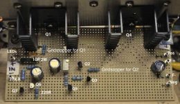
B. I was looking the top side photo now, where are R2 and R9 gate stoppers? Maybe in heat shrink under? (Those are doing what grid stoppers do and should be used as grid stoppers for proximity or big instability risks occur as you know from tube builds.)
C. If the input cables from raw are long decouple with 0.1uF right at reg's input.
A. 56-38=18V drop for 111mA load. You measured 2.2V across the 10R R1 in CCS. That is adding 220mA. I.e. 331mA total. That is 3 times. Or 2 times with just the reg. Sure it will hold?
B. I was looking the top side photo now, where are R2 and R9 gate stoppers? Maybe in heat shrink under? (Those are doing what grid stoppers do and should be used as grid stoppers for proximity or big instability risks occur as you know from tube builds.)
C. If the input cables from raw are long decouple with 0.1uF right at reg's input.
The reg was getting 40 V before I replaced Q2.
Don't know what happened.
Now you got a warm Q1 and proper drop across R1. Seems like working after Q2. At least partially for current draw.
So 220mA is 2 times what your test dummy brings to the raw without the reg. Shouldn't it drop another 18V for the reg?...Doug, 39-18=20. Rings a bell?
OK, so you're saying to lose the PS resistors to get back to about 38 Vin right?
I was initially worried about frying all the sandy things, so I didn't want voltage into the regulator to be too high.
I appreciate your evaluation from a distance. I have been so worried about measuring little things and not seeing the big picture of how much current I was drawing.
Efharistó Salas.
Doug
One more thing:
I still want 38 Vin with a 60 mA (28 V/0.06 A = 466 ohm) load, right.
How do you put up with idiots like me? 🙂
Thanks.
I still want 38 Vin with a 60 mA (28 V/0.06 A = 466 ohm) load, right.
How do you put up with idiots like me? 🙂
Thanks.
OK, so you're saying to lose the PS resistors to get back to about 38 Vin right?
Doug
Right. First thing is we have enough Vin and from there we see next. But look on B & C points of thinking while you are at it. (#8548).
One more thing:
I still want 38 Vin with a 60 mA (28 V/0.06 A = 466 ohm) load, right.
How do you put up with idiots like me? 🙂
Thanks.
No worries, I do worse all the time myself.
When such reg works its CCS properly, then its output load changes nothing for its input draw. Its a current regulator wall between input and output sorta.🙂
Doh before, good now if will be moved smack on gate pin. See them stoppers as sandy bridge without Intel I7 price tag crossing over to heater-less pentodes. That will sweeten this bitter pill somehow.🙂
Nah, unless they're round and made of glass, they are just three legged fuses to me.
Maybe I'll glue a 45 tube in there to make it look real. 🙂
I will post again tomorrow.
Maybe I'll glue a 45 tube in there to make it look real. 🙂
I will post again tomorrow.
Good Morning Salas!
Changed the raw PS. Bridge to 4 ohm R --- 100 uF Cap ---- 2H Choke----4700 uF Cap ------ 4 Ohm R ------4700 uF Cap, then to Reg
Initially this raised Vin to Reg up to 30 volts, so I replaced the 10 ohm R1 with 22 ohm to get load down. Vin went up to 47 volts,
Vin = 47 V
Vout = 3.5 V with 500 ohm load on reg and pot set at 1.5 kOhm
V across R1 now 1.8 V (1.8 V/22 Ohm = 82 mA)
V across R4 = 46 V
V across R5 = 0.62 V
Q1 G to S = 3.0 V
Q4 G to S = 3.3 V
Q3 B to E = 0.6 V
Q6 B to E = o.6 V
Q7 B to E = 0.7 V
Q2 G to D = 3.3 V
Q5 G to D = 0.7 V
What's next boss?
Thanks!
Doug
- Home
- Source & Line
- Analogue Source
- Simplistic NJFET RIAA