my understanding is that the source has the "triangle pointing to N" tied to it, so it looks to be correct.
Well I'm off to bad start
Hi Guys,
As usual, once I touch anything solid state, I screw it up.
What I did:
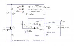
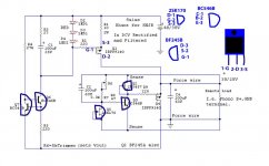
1. Made one piece of Salas LV shunt from the pdf version (and shown below) for moving magnet 38 V in/28 V out
2. Made one raw supply with 18-0-18 Xfr and a dropping resistor to give 40 V loaded with about 120 mA load (333 ohm resistor)
3. Didn't think to check the unloaded voltage of the raw supply.
4. Hooked up the raw supply to the regulator with a 500 ohm load on output of
regulator (28 V/0.06 A = 0.056 Amp)
5. Got no voltage at output, so checked V/in
Yikes! 55 volts.
6. Checked transistors while still connected on board.
Did a diode check with my DMM Found:
Q1 IRF9540 G to S = OL G to D = OL
Q2 BF245A G to D = continuity G to S = continuity (obviously)
Q3 BC546B B to C = OK B to E = continuity
Q4 IRF9540 G to S = OL G to D = OL
Q5 2SK170 G to D = continuity G to S = Continuity (obviously)
Q6 BC546B B to C = OK B to E = OK
Q7 BC546B B to C = OK B to E = OK
OK, so was I supposed to have V/in 38 V unloaded?
Which three leggy things do I need to replace?
How can I avoid doing this again? 🙂
Hi Guys,
As usual, once I touch anything solid state, I screw it up.
What I did:
1. Made one piece of Salas LV shunt from the pdf version (and shown below) for moving magnet 38 V in/28 V out
2. Made one raw supply with 18-0-18 Xfr and a dropping resistor to give 40 V loaded with about 120 mA load (333 ohm resistor)
3. Didn't think to check the unloaded voltage of the raw supply.
4. Hooked up the raw supply to the regulator with a 500 ohm load on output of
regulator (28 V/0.06 A = 0.056 Amp)
5. Got no voltage at output, so checked V/in
Yikes! 55 volts.
6. Checked transistors while still connected on board.
Did a diode check with my DMM Found:
Q1 IRF9540 G to S = OL G to D = OL
Q2 BF245A G to D = continuity G to S = continuity (obviously)
Q3 BC546B B to C = OK B to E = continuity
Q4 IRF9540 G to S = OL G to D = OL
Q5 2SK170 G to D = continuity G to S = Continuity (obviously)
Q6 BC546B B to C = OK B to E = OK
Q7 BC546B B to C = OK B to E = OK
OK, so was I supposed to have V/in 38 V unloaded?
Which three leggy things do I need to replace?
How can I avoid doing this again? 🙂
Attachments
Also, the LEDs did not light up right away when I turned it on, but they flickered on and off while I tried to read some voltages.
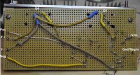
Had any Leds glowing during the test? All BJT semis are 65Vceo so I doubt you killed any. Do you have an up side and underside shot so we may help? Should be some wrong connection its possible.
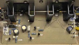
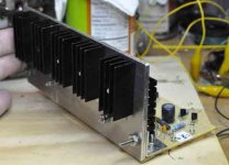
Nice heatsinks 🙂
What material did you use to insulate the power mosfets ?
I bet it's an insulator 🙂
Salas,
Not sure I will get the re-tracing done today, but here are some photos.
Not the prettiest job, I know.
Thank you SO much.
Doug
The frontal sinks could be saved for normal circa 200mA CCS I guess. So to simplify. But it must work first so to evaluate temps. If you will do a continuity test between CCS Mosfet tab and sink screw, is there any continuity by mistake maybe? I will try to spy with my little eye the pics for connections also.
Salas,
Not sure I will get the re-tracing done today, but here are some photos.
Not the prettiest job, I know.
Thank you SO much.
Doug
It may be a good idea to remove the circuit board in/below the 4 'ventilation' shafts of the heatsinks, probably just a bit larger (the hole) than the actual shaft size.
Also, Salas, when I hooked up the raw supply to the reg, I connected the raw ground to Force negative. That is right isn't it?
Also, the ground is floating, i.e. not connected to earth, since it is on a breadboard.
Doug
Also, the ground is floating, i.e. not connected to earth, since it is on a breadboard.
Doug
- Home
- Source & Line
- Analogue Source
- Simplistic NJFET RIAA