No problem, only your dissipation on the CCS Mosfet is gonna go up to 2.2W with 40V DC in. You gonna be secure against off limits mains drop on the other hand.
Re: 28V Led Shunt
Don't know for sure at the moment, off course cartridge channel separation isn't demanding at all, and the shunt has very low output impedance so not to let channels inter modulate enough. Someone would say it may pass without a benefit. But Cygnus X1 always uses double supplies and says he can hear it doing better. I will know more soon, because we are planing with Michael a good build with subjective tuning on good parts selection and two LED shunts with two 100VA mains toroids in a full width box. It has already started. A few stuff from Ebay and we will know what benefits and what is not.
RCruz said:Hi Salas
Should I build two shunts (one for each channel) or is it overkill ?
Ricardo
Don't know for sure at the moment, off course cartridge channel separation isn't demanding at all, and the shunt has very low output impedance so not to let channels inter modulate enough. Someone would say it may pass without a benefit. But Cygnus X1 always uses double supplies and says he can hear it doing better. I will know more soon, because we are planing with Michael a good build with subjective tuning on good parts selection and two LED shunts with two 100VA mains toroids in a full width box. It has already started. A few stuff from Ebay and we will know what benefits and what is not.
salas said:
You can even bypass R1 (the 100R resistor under first stage JFET) with a 1000uF Panasonic FC or Elna Silmic or Black Gate NX 6.3V and it will become 41dB gain without further changes.
That easy ? 😀
I will try that. admitted, i don't have any "high grade" stuff, but will, as a test, use a couple of Frako's i have in stock.
Thanks a lot for advise Salas.
Best regards
Ebbe
es44 said:
That easy ? 😀
Yes it will work that easy. It is just not the best way if you have a very good system and you are looking not to listen to any electrolytic capacitor sound quality. On the other hand, in tubes world such ways are used and many people even ''cook'' their tone using parts quality sonic colors.
Try with the Frakos, and if your system has the analysis to still show any cloudy quality of them after 48 hours of play, just parallel one little (sub 1uF) film cap across each Frako. It will open up.😉
HI Salas
the shunt I still make for driver stage are one for channel as diode and caps but with only one trafo
the shunt I still make for driver stage are one for channel as diode and caps but with only one trafo
Just want to thank you guys for all your help again, I've finished the prototype last night. It's a bit too early for comments, since I haven't had the opportunity to listen much to it. However, the initial impression is tight strong bass, ok highs, but not great mids. I don't mean to say this as a negative comment; the preamp sounds very clear, nice tone, but just didn't hear that "special" sound yet. More tuning is in order.
Unfortunately in the batch of jfets I had there were none with an Idss of 7-8mA, all were higher. Another batch of 100 pieces came today, so I'll be doing more matching soon.
salas, would you say that all of the four jfets should be in the 7-8mA, or just some?
Unfortunately in the batch of jfets I had there were none with an Idss of 7-8mA, all were higher. Another batch of 100 pieces came today, so I'll be doing more matching soon.
salas, would you say that all of the four jfets should be in the 7-8mA, or just some?
Only the gain stages JFETs must be matched. The buffer one and the Zener CCS one, no problem. Just don't use extremes for those.
Wait for 48 hours of total play before you substitute any passive part. It will open up and mellow significantly.
For nice mids, your R input load, 47k series RIAA resistor, 16n RIAA cap and interstage cap are crucial. At least Kiwame, Silver Mica, and K40u-9 PIO. Also listen without your extra 150pF input cap. The Grado has low inductance, I don't think that the cap is doing any good there.
Hey, hey, hey, RCruz decided to take the situation in control! Congrats. Get a black pen and touch up any tiny voids in black if you have...
ikoflexer said:I've finished the prototype last night.
Pictures? Wanna know what parts you used so I can help you with tuning.
Re: 1st PCB ever
Excellent work Ricardo.
I can only apologise for the massive delay with your board, I really am very sorry. I just sent you an email.
Last night, for the first time in months I managed to have a play with my Phono stage. I fitted a discrete, low-noise reg and rearranged the psu to shorten and neaten the wires up.
It now really does sound great, I'm really impressed Salas! For the coupling cap I'm using a 0.1uF Mundorf Supreme, and I'll swap that for a 47nF Russian PIO when I get chance to compare.
I also fitted extra Rubycon ZA's accross the one's already fitted. Doubling each one's capacitance to 440uF. This seems to have given better dynamics. Are larger uF caps much more beneficial?
Cheers, Lee.
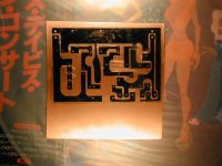
RCruz said:My first atempt on the schunt pcb.
It is the pdf image in negative
Hope the circuit is ok.... I had to hand paint everything over the lazer transfer because it was full of flaws.... I added some gotic artwork !
Ricardo
Excellent work Ricardo.
I can only apologise for the massive delay with your board, I really am very sorry. I just sent you an email.
Last night, for the first time in months I managed to have a play with my Phono stage. I fitted a discrete, low-noise reg and rearranged the psu to shorten and neaten the wires up.
It now really does sound great, I'm really impressed Salas! For the coupling cap I'm using a 0.1uF Mundorf Supreme, and I'll swap that for a 47nF Russian PIO when I get chance to compare.
I also fitted extra Rubycon ZA's accross the one's already fitted. Doubling each one's capacitance to 440uF. This seems to have given better dynamics. Are larger uF caps much more beneficial?
Cheers, Lee.
Hi Lee
Just read your e-mail. I am glad you did the board for me as well as source the dificult caps.
Regards
Ricardo
PS: Tonight I will put the shunt PCB on the etchant...
Just read your e-mail. I am glad you did the board for me as well as source the dificult caps.
Regards
Ricardo
PS: Tonight I will put the shunt PCB on the etchant...
HI Cruz
I see that you mod a lot your meridian ......
by the way he have metal shield around phono ,a simple psu design and one opa-amp ,buffer?
I thinks the Salas phono-shunt are super design ,DIY are always better 😀 you want connect in the meridian ?
you can thinks a pot like otptivol and connect direct to amp
best
Re: Re: 1st PCB ever
With the Shunt, not that beneficial. With other PSUs yes, the bigger (up to 1000uF), the lower in frequency they will decouple the power source impedance and the more energy they will store. Depends on their quality for optimum. I would say that about 470uF Nichicon KG can be nice, or 1000uF BG NX.
Thomo said:I also fitted extra Rubycon ZA's accross the one's already fitted. Doubling each one's capacitance to 440uF. This seems to have given better dynamics. Are larger uF caps much more beneficial?
Cheers, Lee.
With the Shunt, not that beneficial. With other PSUs yes, the bigger (up to 1000uF), the lower in frequency they will decouple the power source impedance and the more energy they will store. Depends on their quality for optimum. I would say that about 470uF Nichicon KG can be nice, or 1000uF BG NX.
nicoch46 said:HI Salas
what you thinks about a JC buffer for how need ?
Very good buffer. The less the 1K input resistor can be with your input cabling (its there to protect from possible oscillations) the more open it will sound. Maybe you can do well with 220R if carbon and attached directly to the JFET pin.
salas said:
Pictures? Wanna know what parts you used so I can help you with tuning.
Sadly, I was very busy with work and other stuff at home, but I'll post pics soon.
I have no boutique parts, unfortunately. All the parts I used were regular stuff. The electrolythic caps I measured for low ESR. The resistors are generic metal oxide. The .1u interstage cap is polypropylene.
You mentioned the 150p input capacitor. I only made room on the board for it, but never used it. I will try an input resistor smaller than 47k, it may make a difference.
I listened to the phono again last night, after I fitted a pair of newly matched sk170s. The same impression, great bass and highs, but the mids are sort of lifeless. It is especially evident when playing some classical music and a couple of violins play together.
Re: 1st PCB ever
Nice board Ricardo! Well done. Once you find the proper paper for the transfer, you will not see many flaws at all. It is also important to press decidedly with the iron edge (or tip) in one place repeatedly, Also, when printing it, the printer has to be set to the darkest setting (done in properties in software, advanced option). They also sell special transfer paper in electronics parts stores, but it's a bit pricey.
When I have to retouch, I use black nail polish (donated somewhat reluctantly by my wife 😀 ).
RCruz said:My first atempt on the schunt pcb.
It is the pdf image in negative
Hope the circuit is ok.... I had to hand paint everything over the lazer transfer because it was full of flaws.... I added some gotic artwork !
Ricardo
Nice board Ricardo! Well done. Once you find the proper paper for the transfer, you will not see many flaws at all. It is also important to press decidedly with the iron edge (or tip) in one place repeatedly, Also, when printing it, the printer has to be set to the darkest setting (done in properties in software, advanced option). They also sell special transfer paper in electronics parts stores, but it's a bit pricey.
When I have to retouch, I use black nail polish (donated somewhat reluctantly by my wife 😀 ).

- Home
- Source & Line
- Analogue Source
- Simplistic NJFET RIAA