That is another good idea. I think Wavebourn has a few posted. I am still at a loss as to how it works.
I wouldn't do that. Use 63-66dB for a 0.2mV cart. Your CDP cruises at much lower VRMS than max out. Your vinyl cruises at nominal cart output. All you get is a noisy and rather offensive result if you pursue 80dB gain for 0.2mV. Just my 2 cents.
Thanks for the suggestions...
are you sure that the CDP delivers lower output signal than 2.0Vac... I mean the 80dB including the head amp.
It would only draw around 50mA. To suck 500mA it would need to be 100R and to dissipate 25W. Would need a metal body big one on a heat sink. Like building a Zen amp with resistor CCS.
I would put 10R R1 in a working V1 reg for circa 200mA CCS to test the 10R to Cfilter already installed. If it drops around where you want for DCin to reg given your mains and trafo, I would then set it back to 3R8 R1 for 500mA CCS and use 2R7 15W to Cfilter.
I changed BJT's Q6 & Q7 + burned R5, I connected 10R R1 for 200mA CCS with 10R Cfilter & now is working well with 5k trimmer can get easy 55VDC with 1k 5W load.🙂
Can be enough power for 2R7 Cfilter (1R5 10W + 1.25 12W connected in series)
Merlin, I would recheck the LED's as well, makes sure they are still matched. A color change isn't a good thing in an LED since they are typically mono-chromatic unless it is designed to do that. If not, the junction was over heated. The Orange glow was probably thermal emission and not normal.
In regards to the gain comment presented earlier. If there was more gain than the 58dB I allready have, my speakers would have glowed like the LED above at the same volume settings as my cd player. As it stands now, my volume control is very much in the same range as my cd player for the same volume.
I have some pictures coming of the DL103r on the arm and comments on the RD80 mod. The mods I did were in the wrong direction so don't get too excited.
I spent the day redesinging my 12b4 preamp. It was an old project using bird nest and dead bug technique. The bugs started to rot in the nest, if you know what I mean. I put the tube on a 10m45s CCS load with LED bias. Working well so far, at least the gain between channels is closer.
Thanks for the input about leds, as Salas advice I changed BJT's + resistor & now is working properly🙂.
In mine case the phono Salas Simplistic NJFET RIAA has more gain than mine DAC due to the fact that I'm using pasive I/V resistors.😀
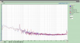
Finally got around to measuring the test lp today. In general I am not overly impressed with my isolation of 60Hz and associated harmonics. See attached. I'll let you judge and offer suggestions.
I can see that the Arm Resonance is 10.5Hz which was close to Salas predicition. I also see alot of rumble.
What I find interesting is that the 60Hz + Harmonics is not audible. Certainly measurable. I used the same basic set-up and cables as I did with the 12b4A preamp pesurements (which I had good measurements) so this time I feel it is related to the TT, Cartridge, and Head amp.
The attached files are:
1) Grounded Input
2) Arm Lifted
3) Un-Modulated Track
4) 1kHz 0dB
5) 100 Hz 0dB
6) 1kHz -20dB
7) 10kHz -20dB
In all the plots I overlayed L and R channel. Very insignificant differences.
Now I need to get rid of the ground loops. P.S. I do have a gnd lug on preamp now and was used.
Attachments
-
 No Signal Input Gndd L_R.jpg197.5 KB · Views: 287
 -
 No Signal Arm Lifted L_R.jpg204.2 KB · Views: 297
 -
 Silent Groove L_R.jpg197.4 KB · Views: 287
 -
 1kHz 0dB L_R.jpg196.1 KB · Views: 281
 -
 100Hz 0dB L_R.jpg197.7 KB · Views: 290
 -
 1kHz -20dB L_R.jpg196.6 KB · Views: 160
 -
 10kHz -20dB L_R.jpg198.8 KB · Views: 163
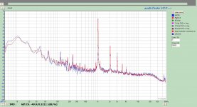
plot7 shows 40kHz passing right through the whole system. That, for me, confirms that the phono replay system must strive for a flat response to beyond 40kHz to keep all the different components of the signal in the correct ratios.
I also note the odd harmonics of the 60Hz mains frequency. I wonder if this is worth chasing further, or are you reaching the limit of what can be suppressed?
I also note the odd harmonics of the 60Hz mains frequency. I wonder if this is worth chasing further, or are you reaching the limit of what can be suppressed?
Analogue Productions "The Ultimate Analogue test LP"
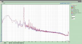
Here I attach a 300HZ +12dB modulated groove FFT with 103R on Mission 776 arm and Walker 58 TT. Gain=61dB. Also the residual FFT of the locked groove on track's end. Test LP is HFNRR. Phono & TT on rack, many different mains and signal feeds very near.
I first posted them in an interesting mini research for what's to get from a record in that thread. Interesting to read a bit further there and to see some more measurements and talk from some more members.
Now if such harmonic pick up as you show is really happening in the audio system or in your FFT test loop, I don't know, can't judge from afar.
Attachments

Andrew, please ignore anything above 40kHz. That is an artifact of the test set-up.
I am not sure what you mean regarding the odd harmonics of the 60Hz mains. I would hope that this could be improved. I have never measured a TT system before, so my baseline is Line Level and amps. I am not sure what is good or bad.
I am not sure what you mean regarding the odd harmonics of the 60Hz mains. I would hope that this could be improved. I have never measured a TT system before, so my baseline is Line Level and amps. I am not sure what is good or bad.
plot7 shows 40kHz passing right through the whole system.
There is no ''lost constant'' zero adding resistor thing in his CCT, its a straight Lipshitz RIAA so I would be doubtful about the filter passing that. Could be a card+software thing as well.
I can clearly see isolated peaks at 10, 20, 30 & 40kHz, before the rubbish comes in.
That to me seems like all frequencies upto 40kHz are passing straight through the reproduction chain. The rubbish prevents me seeing evidence of what is passing in the range 41kHz to 100kHz.
The odd harmonics of 60Hz are at 180, 300, 420, 540Hz. I can see them in addition to the 60Hz in plot1. Are there 660 & 780Hz in there?
You said they were inaudible.
That is what made me suggest whether they are worth chasing.
Last edited:
I can clearly see isolated peaks at 10, 20, 30 & 40kHz, before the rubbish comes in.
That to me seems like all frequencies upto 40kHz are passing straight through the reproduction chain.
I would ask Scott if there is some octave scaling going on in the software for those charts?
P.S. On the last pic he actually replays a 10kHz tone.
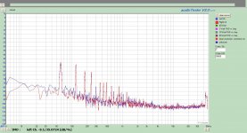
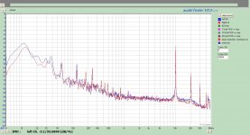
Okay here are some tests using the HFN test lp. Sames tracks as you posted Salas. In addition put the pink noise on as well.
I put the scales the same as well. I can creat the full range if needbe.
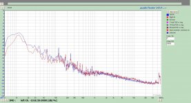
I do see a difference between channels using the pink. Right has little more pick-up in higher frequencies. That does compare favorably to my listening experience.
I put the scales the same as well. I can creat the full range if needbe.
I do see a difference between channels using the pink. Right has little more pick-up in higher frequencies. That does compare favorably to my listening experience.
Attachments
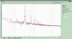
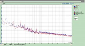
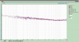
Those settings clean things up I see. Looks much more agreeable now. My 103R has more last octave HF hump on R than L too. But it best averages between L&R after being run in, azimuth and anti skating is reset for all 3 bias tracks spanning start-mid-end of the 2nd side of HFNRR test disc. TT levelling will play a role also. But see your 15n Riaa capacitors are surely matched first of all.
P.S. If I lift the arm the mains double harmonic isn't there. It passes on the record, must be the motor. Your TT is a bit fast, mine a bit slow the FFTs say.
P.S. If I lift the arm the mains double harmonic isn't there. It passes on the record, must be the motor. Your TT is a bit fast, mine a bit slow the FFTs say.
- Home
- Source & Line
- Analogue Source
- Simplistic NJFET RIAA