Nick glad to know a secure source on sound of dl103r ....in the web 50% like - 50% dislike.....waiting more info vs 160 as I know how sound ....tube itch too😉
iko with jfet no dc on cartridge, the same with bjt ?
ps
95db !? new speakers ?
iko with jfet no dc on cartridge, the same with bjt ?
ps
95db !? new speakers ?
Last edited:
iko with jfet no dc on cartridge, the same with bjt ?
Doesn't matter, the MC still presents a low source resistance to the next gain block. Some bjts simply offer lower noise factor (a measure of both current and voltage noise) than the best jfets. But let's not worry about that.
Nick glad to know a secure source on sound of dl103r ....in the web 50% like - 50% dislike.....waiting more info vs 160 as I know how sound ....tube itch too😉
ps
95db !? new speakers ?
Its a controversial beast as it seems on the tonearms of many. The basic 103 as I saw browsing a bit about it today, used to work on the Mission fine, back in its era, so the result is backed up by more experiences also. Tracked well in to the highest modulation of band 10 side 2 of the Telarc Omnidisc, so its a fact, they work together. There the 160 buzzed earlier and stronger. Maybe the high VTF and conical needle takes it better. Listened to it more today, its interesting I get no iritation from a totally new cart, so fastly and basically set on the TT. Even the DIY finger lift provides a little interface between 103R's not that rigid body, I did not tighten the aluminum screws hard also, as recommended by anecdotal experiences. I must go put my ear 10cm from the tweeter to hear the hiss from the sensitive speakers at highest level I replay, not max, even if I just use the standard 56dB simplistic version with just one SK 1st stage and R source C bypassed for 60-61dB gain. All went fortunate for me. This cart is well above 160's league, I hear this clearly. Its coherent and gentle with everything happening easy to hear too. Me I measure the resonances with FFT, the FR with the chosen loading, the noise floor, I know and can change the phono etc. so maybe I have better control and understanding of what I do than just guessing the system, as some web sourced anecdotal cart/arm/TT references, always I start with the test disc on FFT and phono gain, loading, earthing, and then go to music. I could tell and address the reasons if it would set and sound sub optimum. I had mass mounting interface plaques ready if the resonance proved high, mass ring for the counterweigh can make. Was just fortunate I did not need them. Although I will test a counterbalance mass ring so to have the counterweight nearer to the bearings since it takes to unwind it enough for the weight difference of the 103R over the 160. I will know more when it plays 50 LPs or so, but a good start is half the story usually.
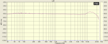
P.S. My speakers were 95dB before, same speakers. PHL 6.5 inch mid.
 ,can sound only better ..
No, its 4 Ohm in the upper bass to low mids, has double eliptical car woofers in closed lower separate box, takes 20W P-P to have grip. Its sensitive but not that light. The voice coils are heavy and the cones too. Stands 300W RMS max.
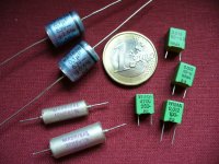
Thank you Salas, Ricardo and Nicoch for you comments about caps.
I'll go for Obbligato (Cout), FT-2 (interstage) and the pictured teflon "by Madrigal" plus some tiny PP film & foil Ero/Vishay KP1830 in // to reach the requested value in the passive riaa.
Russian and Chinese caps ordered today.
Yesterday morning I designed a 3D pcb a la Disco around the two biggest caps (to be placed under the board). Then, as Salas is going to play around a 4 2SK170s at the input in order to increase gain/reduce noise, I already extended the pcb to host the 4 input critters 😀
It may become useful in a while. 😉
Attachments
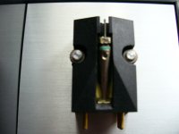
Denon 103 mods
Many years ago (1986), J. Hiraga sugested a simple mod for the Denon 103 in order to reduce body resonances. I performed this mod on my first 103 without open the cartridge with a sharp knife (and a big magnifier lens). Simple and effective.
(sorry for the quality of the picture)
Many years ago (1986), J. Hiraga sugested a simple mod for the Denon 103 in order to reduce body resonances. I performed this mod on my first 103 without open the cartridge with a sharp knife (and a big magnifier lens). Simple and effective.
(sorry for the quality of the picture)
Attachments
Thank you Salas, Ricardo and Nicoch for you comments about caps.
I'll go for Obbligato (Cout))
Hi Massimo
I am using 4.7u obbligato gold and these sound very good.... you must let them burn for a while because initially they are quite rough.
Hi massimo
Can not see the mod... would you care to explain in plain words ? 🙂
Quite easy..... Can you see the large cut? This drawing from the French mag L'Audiophile explain it better.
Pic A (without dotted line) is the std body, pic C the mod I performed
Attachments
I already extended the pcb to host the 4 input critters 😀
It may become useful in a while. 😉
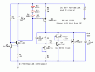
I am going to use a common Rs and high B+ when I will do that. For the time being you can either make pads for a 2200uF capacitor parallel to R2 so you can have what I have now, namely the standard MC version with bypassed R2 that will go back to 56dB for circa 0.5mV MC by just disconnecting the cap, you can even put a mini pcb switch there to its ground leg, or gear up for the following in the pics but for low MC only. Needs some moves with some values to go lower gain. No instant switching capability or a little desoldering for two components. But better noise.
Attachments
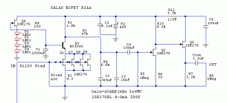
Oh, oh.....Q6 now 2N5459: different pin out
Than R9 added, C1 much bigger (if Silmic, it will be huge).... a deeper revision needed.
R3 no longer 43k? 47k as in the MM version?
R2: if you use a common resistor for the 4 critters, they must be absolutely identical (difficult to match) while a splitted resistor allows for some imbalances. Do you think it's a real advantage?
Shunt: back to v.1? no v1.1?
Q3: BC550? No MJE340?
C4 reduced value?
2N5459 looks better for Vt. *But we can't take advantage since it is 25V device, so 2SK170 in the end. 39V there. On TO-92 sink.
R3. Different Rload before it, must compensate.
R2. Syn08 has shown that it works with even relaxed matching in his HPS3. You can use 4x1R before they meet R2 so they can share current even easier if in doubt, since you make PCB. They can always be jumpered if it ends up the same.
R9. Helps to avoid any noise by feeding the cap in the cascode base, especially with relatively low impedance leds, and low Vp 2SK.
BC550 q3 in shunt higher hfe, if using sink it can take it. C4 220uF terminates OK with 9140 and 46V.
I saw difficulty in simulation for 1.1 at such a voltage. So I can't say do if I don't first.
All I know for sure right now is that the standard 56dB works with the 103R with bypased R2 at 36V V1.1 with 8.2k buffer's emitter load. And that is all I can surely recommend for now.
Salas
searching around the web I see people use 140 to 180r to 500r to 840r 😱
burn in min 15h
After some little run in I tend to settle around 150R now it has opened up a bit. Sounds heftier around that load. Its system dependant, I would say 150-270R should be the play area for those with a 103R. VTA is best with the cart's body parallel to the record's surface and only a tiny bit nose down. Almost a hair. Here it is in 1/48 octave resolution.
Attachments
I change Rload to 100r and have 2200uF R2 bypass for my 0.2mv 2 ohm Supex 909. With little burn in time, I hear better clarity, firmer bass and better seperation/layering 🙂. It may change with more run in though.
What 2200uF? I like Nichicon FG, Chemicon KY, KZH. For industrial caps.
P.S. Did you fix shunt V1.5?
P.S. Did you fix shunt V1.5?
I had 16v Pana FM there...those are what I have in my parts bin.
I replace almost all jfets/bjt and still could not revive it🙁. It must have been one or both burnt mosfets. One other think that I realised is that when it failed, it passed Vin as Vout to the load. This could potentially damage the load because of over voltage. Maybe a over voltage protection is required to be implemented.
I replace almost all jfets/bjt and still could not revive it🙁. It must have been one or both burnt mosfets. One other think that I realised is that when it failed, it passed Vin as Vout to the load. This could potentially damage the load because of over voltage. Maybe a over voltage protection is required to be implemented.
Pana FM very good. Maybe your mids fleshed out too, now.
For V1.5 I don't know details since Iko did that version, maybe you can ask his help on the relevant thread...Or make directly his V2 R5?
For V1.5 I don't know details since Iko did that version, maybe you can ask his help on the relevant thread...Or make directly his V2 R5?
- Home
- Source & Line
- Analogue Source
- Simplistic NJFET RIAA