Hi
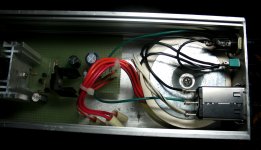
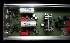
In my case, C3 and C4 are 100n MKP but you can use something between 22n and 100n.
The rectifiers are Hexfred HFA08TB60PBF, Ultra fast / Soft Recovery 8A so these do not need bypass caps.
I am using 15000u 63v Jensen 4 pole for smoothing... great caps provide better high freq definition improving soundstage width and depth a lot.
Nevertheless, the important message is the GND connections in the pdf.
Using two bridges and two smoothing caps with the same TX winding can produce hum if the caps are not locally connected together. The minus must meet and from that point, the wire can go to star gnd. The component values are irrelevant.
Regards
Ricardo
well... not so irrelevant because these components act together with the shunts so all components where chosen after severall tries of course.
Ricardo
Ricardo
still worried with C2 on the shunts, I decided to replace them by 680u BGNx... Compared with the Rubycon ZL it is much wider and the bass has finally acceptable volume and presence.
I will report after some burning.
Ricardo
I will report after some burning.
Ricardo
New Salas RIAA with shunt is born
Hi all,
Haven't posted in this thread before, but I've been watching and I completed my build this weekend. Just got to listen tonight. Having fun so far. I think I need to do some work tracking down a very low level buzz. I've got to get the volume control turned almost to max to hear it. Thanks for all the effort so many of you have put into this project.
Regards,
John
Attachments
Very nice. Your buzz is more probably the trafo field. Cheers.
P.S. I like the cut ic bases for fixing loads touch. Did you listen with the box top fixed? It normally lowers the field.
P.S. I like the cut ic bases for fixing loads touch. Did you listen with the box top fixed? It normally lowers the field.
My signal ground is isolated to the circuit board. Ground from the power cord is only to the chassis. Do you think I should connect signal ground to chassis ground through a resistor or capacitor? The buzz is very low but I'd like to fix it. I'll experiment with different things and report my results. I didn't use a large filter cap in the raw power supply, only 470uF. The raw supply has about .6v ripple on my DVM but the 27V DC at the shunt has no measurable ripple with my meter.
I repeat.
Did you listen with the box top fixed? It normally lowers the field.
Do you think I should connect signal ground to chassis ground through a resistor or capacitor?
Certainly. Fix directly. Take off point from where it meets the shunt's ground.
I also thought about the toroid proximity, yeah, it's possible.
John, do you connect now the phono stage signal ground to the amp signal ground, which then is connected to the pwr ground?
John, do you connect now the phono stage signal ground to the amp signal ground, which then is connected to the pwr ground?
I also thought about the toroid proximity, yeah, it's possible.
Not only possible, seen it again, have measured 1 box and two box builds and debugged buzzes with the aid of FFT.
He must listen with box's top on, and if it makes a difference but still there, then must rotate the PTX untill best.
Thanks to all for comments.
No I haven't listened with the top on yet. I've only listened for about 20 minutes and then pulled out to take a few pictures. I'll try it with the top on next. I will also try connecting the grounds. My turntable doesn't have a separate ground wire but I can connect one to the turntable chassis, or try a clip lead for starters. I'm sure this can be remedied. I just need the time to work on it.
Regards,
John
Sure, only make one expreiment at a time, so not to lose track. Your 0.6V ripple the shunt eats for breakfast, the buzz isn't on the power line, the main filter value changes the juice supply rate and has some impact on your final tone. Will be interesting to hear it with just 470uF when you get it debugged. Is it for a high MC cart? What is your setup?
Your 0.6V ripple the shunt eats for breakfast
Oh yeah! And here's a little experiment I did that should give people an idea of what the shunt can eat for breakfast 😀 The other day I was testing a high power shunt, I wanted to get about 35V at 3A. Maybe not high power for others , but ask the shunt mosfet how it feels to dissipate 90W. In any case, it turns out that I had a CLC filter after the rectifier, that fed the shunt. C1 was 100uF, R was 22R, and C2 was 10000uF. Not needed, but it was there so I used it to power the new shunt regulator prototype. The transformer was beefy, and put out about 46V at the filter output without a load. Well, when I started to raise the current in the shunt (started low at about 100mA), passing 1.5A, I noticed that the voltage started to sag. That's because too much voltage was dropped across the 22R filter resistor. So I used a 2.2R resistor instead, and still, as the current went up, got enough voltage drop that I just took it out and left the caps alone. Changed the shunt and set it to 20V out, and the ripple at the output was insignificant, below 100uV. I should try the shunt with a smaller cap too.
Another fun fact 😀 In a very optimistic moment I turned the current way up, to about 4A. The heat sink was not exactly appropriate and the poor irfbc40 (to220) started to smoke. Turned it all off and looked closer. It was the plastic washer that isolates the mosfet from the heat sink that melted and started to smoke, not the mosfet; the mosfet survived!

Is it for a high MC cart? What is your setup?
I built it for HO MC. I plan to buy a Denon DL-160. Right now I have a Stanton 681EEE (in a Thorens TD-160) which doesn't need the extra gain, but my DIY tube system is a little low on gain so the extra doesn't hurt.
John
Oh yeah! And here's a little experiment I did that should give people an idea of what the shunt can eat for breakfast 😀 The other day I was testing a high power shunt, I wanted to get about 35V at 3A. Maybe not high power for others , but ask the shunt mosfet how it feels to dissipate 90W. In any case, it turns out that I had a CLC filter after the rectifier, that fed the shunt. C1 was 100uF, R was 22R, and C2 was 10000uF. Not needed, but it was there so I used it to power the new shunt regulator prototype. The transformer was beefy, and put out about 46V at the filter output without a load. Well, when I started to raise the current in the shunt (started low at about 100mA), passing 1.5A, I noticed that the voltage started to sag. That's because too much voltage was dropped across the 22R filter resistor. So I used a 2.2R resistor instead, and still, as the current went up, got enough voltage drop that I just took it out and left the caps alone. Changed the shunt and set it to 20V out, and the ripple at the output was insignificant, below 100uV. I should try the shunt with a smaller cap too.
Another fun fact 😀 In a very optimistic moment I turned the current way up, to about 4A. The heat sink was not exactly appropriate and the poor irfbc40 (to220) started to smoke. Turned it all off and looked closer. It was the plastic washer that isolates the mosfet from the heat sink that melted and started to smoke, not the mosfet; the mosfet survived!
Iko you started your Vietnam tests again! Its an unstopable urge, isn't it? Almost a hunger.😀
Attachments

Hi
In my case, C3 and C4 are 100n MKP but you can use something between 22n and 100n.
The rectifiers are Hexfred HFA08TB60PBF, Ultra fast / Soft Recovery 8A so these do not need bypass caps.
Ricardo
sure? I see some use 0.22µf for bypass........
- Home
- Source & Line
- Analogue Source
- Simplistic NJFET RIAA