If you will look some pages back a member used higher voltage spec DMOS and higher value ref resistors and succeeded. Gave some practical account of how he did for low Vout drift at so high Vout also.
Sure. Not same low capacitance but not bad. There are IXTP 02N50D (500V 250mA) IXTP 08N50D2 (500V 800mA) and IXTP 01N100D (1000V 100mA) also.
Thanks, Salas, will take a look at it.
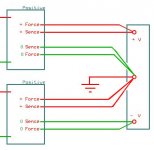
For making (+)/(-) you can only stack them like batteries using two secondaries and two bridges. Their middle point will be virtual zero. Like we do with SSLV1.1 some times or like they used to do in NAIM NAP 250 etc.
Attachments
Normally the transformer has 225v @0.15A for positive per channel.
Does it mean the negative rail per channel require the secondary winding with 2 x 225v @0.15A?
So I need 4 x 225v 0.15A and 4 x SSHV2 for 2 channels' negative rail 200v dc regulation, right??
Does it mean the negative rail per channel require the secondary winding with 2 x 225v @0.15A?
So I need 4 x 225v 0.15A and 4 x SSHV2 for 2 channels' negative rail 200v dc regulation, right??
Normally the transformer has 225v @0.15A for positive per channel.
Does it mean the negative rail per channel require the secondary winding with 2 x 225v @0.15A?
So I need 4 x 225v 0.15A and 4 x SSHV2 for 2 channels' negative rail 200v dc regulation, right??
Right. To make +/0/- from two positive regulators, independent secondary, bridge, and filter are required for each one. In double mono construction that means four secondaries, four bridges, four filters, four regulators.
Well, from the schematic provided - yes. (English is not my mother tongue, maybe I haven't caught your question's meaning.)I want to know whether the outstage has the same B+ as the first and second stages? Is that 179v??
My opinion - if we copy the original layout - one SSHV per channel for +179V.Do you suggest he put one SSHV2 for the first and second stage and the other SSHV2 for the output stage? I meant per channel.
One transformer per stage. (Again - only my opinion)Also, one power transformer for first and second stages and the other transformer for the output stage.
You shouldn't be fooled by the word "balanced". In the positive rail you need +179V? In the negative rail you need -110V? The positive rail powers all four stages (one value for current). The negative rail powers only the first two stages (another value for current). Saying this - why do you want to use secondaries with the same voltage and current values?Normally the transformer has 225v @0.15A for positive per channel.
Does it mean the negative rail per channel require the secondary winding with 2 x 225v @0.15A?
So I need 4 x 225v 0.15A and 4 x SSHV2 for 2 channels' negative rail 200v dc regulation, right??
Yes, you'll have to use 2 independent secondaries for positive and negative rails. Whether you'll want to use different secondaries/transformers for each channel or not is for your decision.
Dear Salas,
Looks like this one?
Thanks!
Looks like this one?
Thanks!
For making (+)/(-) you can only stack them like batteries using two secondaries and two bridges. Their middle point will be virtual zero. Like we do with SSLV1.1 some times or like they used to do in NAIM NAP 250 etc.
Attachments
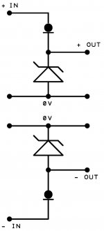
Essentially - yes, but if you are going to build the SSHV on the "official" PCB the "current limiter" part will be in the positive rail for both halves.Looks like this one?
Well, from the schematic provided - yes. (English is not my mother tongue, maybe I haven't caught your question's meaning.)
My opinion - if we copy the original layout - one SSHV per channel for +179V.
One transformer per stage. (Again - only my opinion)
You shouldn't be fooled by the word "balanced". In the positive rail you need +179V? In the negative rail you need -110V? The positive rail powers all four stages (one value for current). The negative rail powers only the first two stages (another value for current). Saying this - why do you want to use secondaries with the same voltage and current values?
Yes, you'll have to use 2 independent secondaries for positive and negative rails. Whether you'll want to use different secondaries/transformers for each channel or not is for your decision.
Regardless the 110v negative rail, how much current the 179v rail drawing from the positive regulator (let's say SSHV2)?
Thanks!
We can only guess. I hope if you have the schematic you may have some explanations/tuning procedure.Regardless the 110v negative rail, how much current the 179v rail drawing from the positive regulator (let's say SSHV2)?
How to guess:
Tubes V1+V3 have (179-[from 40 to 60])/(27.4k/2)=8.7-10.1 mA for each half, 17.4-20.2 mA in total.
V5 has (179-[from 119 to 123])/15k=3.7-4 mA for each half, 7.4-8 mA in total.
V7 is not so obvious, but considering R28, R29 and R19 it should be less than V5, but how much is unknown. I'd use the same values as the top guess, so 14.8-16 mA in total.
Then the whole +179V rail should be something like 39.6-44.2mA (not counting possible biasing current in the power supply if any).
- Home
- Amplifiers
- Power Supplies
- Simplistic mosFET HV Shunt Regs