You go for 200V PS3 out. Alright logical. That Tx will lead to a large rectified voltage figure on PS3 input as the guys above demonstrated though. So a large drop across Q1 on PS3. That means enough W of Q1 heat and a large heatsink. Isn't there a lower voltage transformer to use ending up in say 250V DC rectified max?
The attach circuit is the power supply we have now, and intended to replace with PS3 + SSHV2 for 160vdc regulation.
230vac figure is based on the same diagram, and we can change it to much lower voltage power transformer. What about 180vac @200ma? Is that good enough? The audio circuit is drawing 50-80ma.
thx!
Attachments
180vac is much better. If its a custom tansfo its best you order 150Vac to skip even more voltage drop and dissipation on PS3 and SSHV2. So to rectify at about 200 set PS3 at 180 and SSHV2 at 160
180vac is much better. If its a custom tansfo its best you order 150Vac to skip even more voltage drop and dissipation on PS3 and SSHV2. So to rectify at about 200 set PS3 at 180 and SSHV2 at 160
In what way the PS3 / SSHV2 combo better than the one of above (the circuit I just posted earlier) we have now to regulated the 160vdc?
I can't say when I haven't tested that circuit. You go taste from series to shunt is one sure difference.
You could keep the 230 to 180Vdc regulator and just replace the 180 to 160Vdc regulator with the SSHV
20V across the SSHV will give good performance.
20V across the SSHV will give good performance.
Drop the PS3 and use only the SSHV. You'll have all the goods and no problem. PS3 here is something like the fifth paw. I do not know why did you add it if you even can't figure out what it is for in the combo?
Hi there!
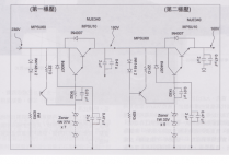
Can anyone help understand what bleeder resistor to use in this PS for 2 SSHV2, please? And why? Each channel consumes 30 mA plus 20 mA for SSHV so the both will total to 100 mA.

Can anyone help understand what bleeder resistor to use in this PS for 2 SSHV2, please? And why? Each channel consumes 30 mA plus 20 mA for SSHV so the both will total to 100 mA.
First of all: Why V1 has only 18V of amplitude if you want to achieve 200V at the output of your filter?
The inductances should have their active resistances too instead of currents (for simulation).
The bleeder resistor is here to discharge the capacitors to a safe level in case of broken connection to the loads (in your case - to the SSHVs). Usually the time for discharging is set to less than 30 seconds, the time could be counted as t=RC, you have 75uF in total, so any value of 400kOhm or less would be suitable for the job.
Thanks, Poty. Actually, it is not a real Spice model, it is here for the sake of showing a schematic. Sorry for the confusion.
I need a bleeder here not only to discharge the caps but also to keep a steady minimum current for the input choke (if I'm thinking the right direction, of course)
I need a bleeder here not only to discharge the caps but also to keep a steady minimum current for the input choke (if I'm thinking the right direction, of course)
I can't understand your intentions. SSHV is a constant current load for your "raw" power supply. I do not know any need for maintaining minimal current for the first inductor, but I may not catch something important in your design.
A choke input filter approaches 1.5Vac as the DC output when current falls.
The normally assumed output of DCV = 0.9Vac ONLY applies over a narrow range of load current.
That current range determines the required inductance. This is critical.
Using a CCS fed PSU ensures a near constant current. That will allow a precise determination of an acceptable inductor.
Using the wrong inductor, or a fuse blowing and removing the load would incur a potentially damaging increase in output voltage to 167% of the design DCV.
Thanks, guys. I really left out the fact that SSHV is CC reg.
But in case of a failure of a reg I want to be sure a critical current is maintained at the 1st choke.
But in case of a failure of a reg I want to be sure a critical current is maintained at the 1st choke.
Last edited:
that's an odd design decision.Thanks, guys. I really left out the fact that SSHV is CC reg.
But in case of a failure of a reg I want to be sure a critical current is maintained at the 1st choke.
It compromises the inductance value required when the load is connected.
OK. What would you advise then, Andrew? In case of a reg failure the first cap will see cap input voltage. I don't like that kind of situation.
If you don't trust your regulator to load down the choke input PSU, then change to a capacitor input and use the lower voltage transformer.
I use CCS fed HV shunt regs. in my DIY gear. The PSs are all choke input. I spec all caps to handle the voltage if the chokes for some reason are not loaded. I also use separate CCS/shunt regs. for each gain stage. If one does fail the other(s) still draw enough current to keep the choke in reg.
- Home
- Amplifiers
- Power Supplies
- Simplistic mosFET HV Shunt Regs