If you like it so much that way,why not do the same thing here :lol
Mona
Instead of focusing on portions of the circuit, why don't you design it with your suggestions in the bigger context of a working regulator, and post it here, with results? Challenging is good, demonstrating and sharing is better, in the spirit of this forum.
Hundreds of DIY's (or more...) have built and are using the SSHV2 with great performance AND listening results. If you believe you have something that would better this proven design, I think everyone would love to see the working model! 😎
To start with I couldn't work out how the circuit could possibly work correctly with such a low voltage across the JFET, but it most definitely does work. 🙂
Alex
To start with I couldn't work out how the circuit could possibly work correctly with such a low voltage across the JFET, but it most definitely does work. 🙂
Alex
Posts #3991-3995-3996 explain.
Posts #3991-3995-3996 explain.
I have finally worked out how to download the linked files and will print and read them!
Alex
I see. My SSHV2 is set to 300V output, so the current through the JFET is 2.2mA. The Idss of the 2SK170bl is 6-12mA so this looks close to optimal.
I hadn't seen this analysis before - very interesting.
Alex
I hadn't seen this analysis before - very interesting.
Alex
Sure it works,I never said it didn't.But not as it shoud,the CCS isn't really one and the zener there is useless.Alex M said:To start with I couldn't work out how the circuit could possibly work correctly with such a low voltage across the JFET, but it most definitely does work. 🙂
Alex
As long as you believe it function well,good for you and the rest of the happy followers.It remains a technical mistake.
Mona
a technical mistake.
By curiosity one can wonder how something that outperforms most competition, are rock solid stable and are easy to DIY can be a technical mistake.
Are we talking religion here?
Staffan
Sure it works,I never said it didn't.But not as it shoud,the CCS isn't really one and the zener there is useless.
As long as you believe it function well,good for you and the rest of the happy followers.It remains a technical mistake.
Mona
You have raised the issue.
So please you, you can make a better modification? and more correct??.
Thank you!
By curiosity one can wonder how something that outperforms most competition, are rock solid stable and are easy to DIY can be a technical mistake.
Are we talking religion here?
Staffan
Well said, except for religion part. THis is audio, afterall😀
I would be more than willing to test any options forwarded, but must confess that I think that some alternative must be presented or else its just farting in the wind.
except for religion part.
I didnt meen to offend about religion per se. I could have said taste, belief, ones standards, cup of tea or whatever. Sorry.
What I ment was that everybody is entitled to one and its not about right or wrong.
In this area, audio and electronics wrong can be things that malfunctions, are hazardous etc. Otherwise what works works.
Staffan
I was just joking, as audio could easily be compared to religion in many ways for the same reasons you listed😉
I used that same zener in my regulators without thinking too much about it, and in practice I know that it saved the jfet (used to have spontaneous dead jfets in that position). But yes, the issue was raised, we should probably address it. Is it an error, in theory, or not? I'm not so sure how a voltage spike would look across the bjt diode in parallel with the zener.
But I don't see it as an error. At the very least the zener will take over more current than the b-e junction which is in series with the base resistor. No?
Instead of focusing on portions of the circuit, why don't you design it with your suggestions in the bigger context of a working regulator, and post it here, with results? Challenging is good, demonstrating and sharing is better, in the spirit of this forum.
I have to agree with the fact that there is a lot more value in considering the entire context as opposed to one small part of the circuit. Some of the important features of the circuit will change even with small isolated changes. I know because we've seen it many times. It's nice to get errors pointed out though.
Yes,look at my reply 3 Aug.page 400.quanghao said:You have raised the issue.
So please you, you can make a better modification? and more correct??.
Thank you!
With the base connected that way the zener make sense to.
Mona
Sure it works,I never said it didn't.But not as it shoud,the CCS isn't really one and the zener there is useless.
As long as you believe it function well,good for you and the rest of the happy followers.It remains a technical mistake.
Mona
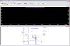
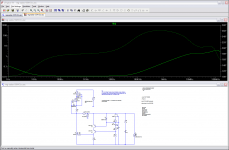
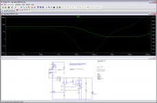
Lets see what LTSPICE says, shall we?
In the OLG pics: CCS as connected originally and as you advise. Connected by your suggestion gives same open loop gain, but 21 degrees less phase margin and more undulation.
In the Zout pics: Orginal circuit, then your bypassed Zener level shift suggestion still with your CCS connection suggestion. I used 100uF as bypass. The output impedance shoots up.
Attachments

Lets see what LTSPICE says, shall we?
In the OLG pics: CCS as connected originally and as you advise. Connected by your suggestion gives same open loop gain, but 21 degrees less phase margin and more undulation.
In the Zout pics: Orginal circuit, then your bypassed Zener level shift suggestion still with your CCS connection suggestion. I used 100uF as bypass. The output impedance shoots up.
As most of us have already experienced, Salas designs in context of complete circuit performance. The proof is in your design, physical results (implementation) and sound performance.
Let's put this to rest.

The fact that it is a technical mistake disturbs me tho. All my gear started to sound fishy. Im thinking of putting some dummies so it looks right.
What is the maximum of the capacitance allowed after the shunt (as part of the load). I of course have the Zobel.
Is it zero, thus no extra decoupling?
In the LV Salas there is seen 220 uF in the initial schema. But I can not find a reference to the capacitance following the shunt. All scjhemas just show the shunt.

albert
Is it zero, thus no extra decoupling?
In the LV Salas there is seen 220 uF in the initial schema. But I can not find a reference to the capacitance following the shunt. All scjhemas just show the shunt.
- I am contemplating 30 uF at 200 V, because mainly it is already part of the schema for each channel of which I am replacing the power supply.
- Could I insert a small resistor before the final cell, say 2 ohms, to break the HF path?
albert
- Home
- Amplifiers
- Power Supplies
- Simplistic mosFET HV Shunt Regs