Thanks for the fast answer! Will probably try this later on if i cant find a better placement for the PCB.
Make sure you got spare semis, since this is beyond prototypes team tested territory, and that extension cabling is inductive in a sensitive place.
You are probably right, but usually PSUD2 is quite spot-on:
I am using a transformer from a reputable source in Germany, multiple members have used it before without problems.
The chokes are specified by the same source as 330Ohm. I have modeled this correctly in PSUD2.
I did some further calculation, and think I could live with 170V input voltage (then I could have 150V output voltage which would work in my application). However I still don't understand this extreme sagging...
Theoretically, if I would have been satisfied with a -say- 10mA@100V supply. I would be looking for 30mA CCS and 100V output voltage. Even that is not achievable now.... I can't get my CCS above 13mA...
You got to debug then. Maybe your CCS is in oscillation in your layout version, maybe some semi is out. Use the scope in main nodes, look for Vgs, Vbe, to be healthy etc. Give the reg a feed from first cap of raw supply to see if something changes.
Hello,
Did a little mistake when ordering part and bought dn2540 to92, so very little current flow... i have some dn2535 to220 on hand, can i use these? Vin is 280v...
Did a little mistake when ordering part and bought dn2540 to92, so very little current flow... i have some dn2535 to220 on hand, can i use these? Vin is 280v...
How many T092 did you bought? Where are you located? We can exchange some if you don't need them...
Hi Salas, I fixed my earlier problem. Turned out I had wired the tube rectifier wrongly.
I have the dual mono shunt regs up and running now. A quick listen gave good results, and scope measurement gave a complete flat line, so virtually noise free.
I did notice that the red LED on one of the regs is much brighter than on the other one. CCS and voltage settings are exactly the same (300mA @ 170V), and I have used the components from tea-bag's component GB (I assume they are the same make leds).
As I said, both measure and sound very good. Do you see any problems I am unaware of?
Maybe 30mA at 170V? The Led is in series with the voltage reference's CCS in SSHV2. For same reference resistors you must be running the same JFET Var CCS current by Ohm's law in the twin SSHV2 regs to have the same output voltage. Odds are you got different Vref resistors by mistake, one different brightness LED, local oscillation that dims the one. But you got a clean rail you say. What is it for? Have you got more pics?
Sorry, indeed 30mA at 170V, both CCS and Voltage set with variable resistors.
What do you mean with "For same reference resistors you must be running the same JFET Var CCS current by Ohm's law in the twin SSHV2 regs to have the same output voltage."
What do you mean with "For same reference resistors you must be running the same JFET Var CCS current by Ohm's law in the twin SSHV2 regs to have the same output voltage."
There are 68K + 68K in series biasing up the cascode error amp BJTs and developing the ref voltage. To have same Vo the Jfet CCS above must be running same Iref. So both leds in the twin regs should be running the same current...
SSHV1
What do you think about osund difference betwwen IRF840 and IRFP450 at shunt position? IRFP450 has twice transconductance, but also twice capacitance.
Is it the same effect as in position where IRF9610 is?
Thanks.
What do you think about osund difference betwwen IRF840 and IRFP450 at shunt position? IRFP450 has twice transconductance, but also twice capacitance.
Is it the same effect as in position where IRF9610 is?
Thanks.
Last edited:
Will change basic parameters. It could even oscillate, but it takes full analysis to predict. Generally expect: Slower, less bandwidth, less output impedance, steeper impedance rise with frequency.
SSHV1 behavior
Hi,
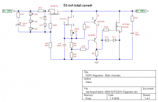
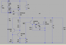
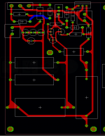
I am having a bit of a strange behavior with the original SSHV design. I configured the circuit so that it would output 300vdc, ~12ma with 350vdc, 45ma input. The regulation seems to work fine, except when connecting and disconnecting a multi-meter to either the raw DC supply or to measure the output. What happens, is that the voltage sharply drops from 300v down to about 150v, until the trimmer is adjusted. I can bring the correct voltage back by turning the trimmer one way, and the voltage jumps back up around 200v. Then I can adjust it back to 300v. If I connect or disconnect a meter, either on the raw or output of the regulated supply, it will again jump back down in voltage. I have two multi-meters, and observe the same behavior when connecting either of these meters to the raw or output voltages. I even have two of these SSHV1 boards, and both of them behave the same way. I'll attach the schematic and board layout.
Regards,
-MW
Hi,
I am having a bit of a strange behavior with the original SSHV design. I configured the circuit so that it would output 300vdc, ~12ma with 350vdc, 45ma input. The regulation seems to work fine, except when connecting and disconnecting a multi-meter to either the raw DC supply or to measure the output. What happens, is that the voltage sharply drops from 300v down to about 150v, until the trimmer is adjusted. I can bring the correct voltage back by turning the trimmer one way, and the voltage jumps back up around 200v. Then I can adjust it back to 300v. If I connect or disconnect a meter, either on the raw or output of the regulated supply, it will again jump back down in voltage. I have two multi-meters, and observe the same behavior when connecting either of these meters to the raw or output voltages. I even have two of these SSHV1 boards, and both of them behave the same way. I'll attach the schematic and board layout.
Regards,
-MW
Attachments
- Home
- Amplifiers
- Power Supplies
- Simplistic mosFET HV Shunt Regs