quanghao, it's very time consuming to check the layout manually. Get the schematic right, then use the layout<->schematic synchronization feature of your layout software.
Yes, i lost alot of many times:
Fist: i draw layout in Adoble inlustrator
secon: I use Protel draw again layout! and check!
You se in my laout is wrong or right??? can you help me??
An I want information about the circuit,:
1. filter of Q3 IRF 840???
2. impedance out put???
Nowaday, I make 5 board, for my pre!
If you like this board I will sent one board to you, one gift for you???
Thank!
Quanghao, the two Q1 "grid stopper" (R470) are too far away from the mosfet gates: try to arrange the layout in order to have those resistors as close to the IRFP9240 as possibl otherwise they are nearly useless.
You can also rotate the two MJE350 by 90 degrees.
my 2 cents
You can also rotate the two MJE350 by 90 degrees.
my 2 cents
Hello Salas,
I've made my first simplicistic regulator and It seems work very good!
I've fitted in my diy CDP as PSU of a the 6C45 output stage.
Now I want to make a 12B4 preamp but I've a question:
I've not found 2N6520 but only MPSA92. How much is the maximum output voltage with MPSA92? What I can use instead of 2N6520?
Actually my regulator, calibrate at about 240 volts on the start arrive at about 310 v of peak. On the 12B4 preamp I must calibrate at 330V.
Ciao
Guglielmo
Try MPSA94 if you can find. That is 400V PNP. MPSA92 is 300V PNP. All those must be sinked with TO-92 minisinks if running it about near 300V or more. Because they become heat sensitive and show erratic behavior. MJE350 is better for taking the heat, and can be sinked easier since it has a more proper packaging type, its limit is 300V though. Also if you want it to behave better around 300V settings, you can use 220k R3, R8 2W and 150R R5 so the BC560 does not have to pass much current to the Vref resistor and its base current is not getting too much. Holding a lot high at startup, has to do with C1 charged. You may try 0.47uF there, but this is something I haven't had to do, so I don't really know, its a test proposition. What do you mean, works very good? Good for noise? What you had before there?
I' m almost ready to build the regulators, have all parts and waiting for disco's design PCBs on Friday.
For C2 and C3 i have some 1μF/400V Wima MKP4 and MKP10.
Do you have any suggestions which one to use?
In your opinion is there any reason to use more power supply decoupling capacitors on the preamp board?
Thank you
For C2 and C3 i have some 1μF/400V Wima MKP4 and MKP10.
Do you have any suggestions which one to use?
In your opinion is there any reason to use more power supply decoupling capacitors on the preamp board?
Thank you
Dear Salas, I was evaluating two of the lastest schematics (#544 and 518) that suit my needs (Vout 220÷240, Iload 20÷30 mA) and I noticed that you add a "grid stopper" with the MJE350 and not with the MPSA92, both used as driver.
Is the resistor needed only with the MJE?
Is the resistor needed only with the MJE?
It looks a bit better with the Mje. Its not a big deal though. But a precaution. What is your experience with the reg by now? Where you use it and how it performed?
It looks a bit better with the Mje. Its not a big deal though. But a precaution. What is your experience with the reg by now? Where you use it and how it performed?
Not build yet..... my idea is to test it with an SRPP phono stage.
Thank you for your recommendations Salas. I hope to build it during weekend.
Not build yet..... my idea is to test it with an SRPP phono stage.
Good luck to both of you. Comments, photos, questions, silly subjective bubbletalk, pranks and comedy are always welcome as you know by now.😀
Only don't take what you hear too seriously OK?

Thank you Salas.
BTW, I'm thinking to build your shunt in 3 versions in the near future: low, mid and high voltage..... 😱 (your Riaa, SSTART preamp, tube SRPP Riaa)
I'll let you know
BTW, I'm thinking to build your shunt in 3 versions in the near future: low, mid and high voltage..... 😱 (your Riaa, SSTART preamp, tube SRPP Riaa)
I'll let you know
Luck be with us!
We want to bring out the finest nuances of the music (as claimed from a company for their capacitors).
Thank you Salas.
We want to bring out the finest nuances of the music (as claimed from a company for their capacitors).
Thank you Salas.
Comments, photos, questions, silly subjective bubbletalk, pranks and comedy are always welcome as you know by now.😀
Only don't take what you hear too seriously OK?
Well, to boldly go etc... I'm set for take off tomorrow.
Stereo 2A3 amplifier on 300V, 50mA per channel and 23mA sunk.
It maybe doesn't sound wild but 14W of extra heat is a lot.
Photos and report are expected tomorrow, if I don't get lost in space 🙂
Hello Salas,
after some tests I burnt all the small transistors on my regulator.
I've repaired but I've a question;
Icss=65mA Vin=340V Vout 240V Iout=38mA Cout=10uF.
There is something wrong in your opinion.
The cap of 10uf after the regulator is too big?
Ciao
Guglielmo
after some tests I burnt all the small transistors on my regulator.
I've repaired but I've a question;
Icss=65mA Vin=340V Vout 240V Iout=38mA Cout=10uF.
There is something wrong in your opinion.
The cap of 10uf after the regulator is too big?
Ciao
Guglielmo
What's the need for that cap?
Your input to output voltage difference is high (100V), heating up the IRFP9240.
Your input to output voltage difference is high (100V), heating up the IRFP9240.
Hello,
I put the cap (10uF) because I've 30cm of wire between regulator and the output stage.
Ciao
Guglielmo
I put the cap (10uF) because I've 30cm of wire between regulator and the output stage.
Ciao
Guglielmo
I put the cap (10uF) because I've 30cm of wire between regulator and the output stage.
From what I have learnt being part of this thread with my silly subjective bubble talk there should be no capacity after the regulator but small B+ decoupling caps (0.47uF) right at the "consumer side".
Make shure to twist that 30cms of wire (make a nice rope of it 😀) and you shouldn't have problems... I cured some oscillations I had in my reg that way.
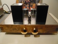
My preamp plays better than ever. It has less noise (still has some hum though), better dynamics, better soundstaging and the sound has a better "flow" to it. If I where to critisize the bass may be a bit thinner but though a lot more precise. The new reg replaced a tube-based reg where I used the 6N1P tube in the pic.
Attachments
- Home
- Amplifiers
- Power Supplies
- Simplistic mosFET HV Shunt Regs