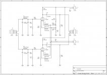
He posted the schematic a few pages ago.
Both channels make the eeee sound? You can power them one by one, and see what's going on.
Both channels make the eeee sound? You can power them one by one, and see what's going on.
Found it. First thing I would do is to add local decoupling very near to the anodes. Beeds and stuff looks like having, I don't now if they are in. I would like to see stoppers though on the extra grid pins.
Ok! you can see my layout!
Attachments

Will have a closer look later. Do you have in better analysis?
What do you want to say?? I think my layout is not good for tube 6c45! I have to fix it
What do you want to say?? I think my layout is not good for tube 6c45! I have to fix it
Later. I will be absent now. Takes much time. Meanwhile many tube people who frequent here can look. Only post a bigger one to be easier to read.🙂
Good night. Don't forget your portable radio!
An externally hosted image should be here but it was not working when we last tested it.
Show us the schematic. Is there any active load? Those can interact.
The two heatsinked devices (silver heatsinks) you can see in the preamp pcb look like a pair of LM317 configured as CCS for the tubes heater. Not shown on schematic
Last edited:
The two heatsinked devices (silver heatsinks) you can see in the preamp pcb look like a pair of LM317 configured as CCS for the tubes heater. Not shown on schematic
They could be individual heater Iregs, I don't see the Rset and I don't see the plate load resistors on the photo though. Nor the antiparasitic beed chokes. I see 2X470R for grids close enough non the less on the cct, not on the photo. This one takes hands on debugging and good info. We can not derive much like that.🙁
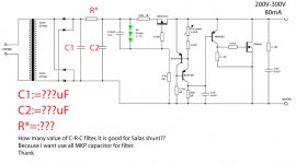
Using a CRC or similar is mandatory before the Salas shunt in order to cut down ripple. Values you have to find yourself... best by using PSUD2 which is a great tool to simulate things easily. A good starting point would be something like 220uF-500R-220uF but it very much depends on the power transformer you are using. Do not forget to allow ~50V across the regulator and use at least a 10W resistor in the CRC.
Using a CRC or similar is mandatory before the Salas shunt in order to cut down ripple. Values you have to find yourself... best by using PSUD2 which is a great tool to simulate things easily. A good starting point would be something like 220uF-500R-220uF but it very much depends on the power transformer you are using. Do not forget to allow ~50V across the regulator and use at least a 10W resistor in the CRC.
Ok! thank!
So Use alot of MKp cap!
You can share for mee, in your pre use Salas shunt??
What is pre or Amli use Salas shunt???
EX:
quanghao,
I am using Salas reg in two headphone amplifier (c this thread).
Works absolutely troublefree!
I am using Salas reg in two headphone amplifier (c this thread).
Works absolutely troublefree!
Has anybody done a comparison of this shunt reg against Swenson/Gary P's series Mosfet reg? Disco, I think you have tried both?
quanghao,
I am using Salas reg in two headphone amplifier (c this thread).
Works absolutely troublefree!
Ok! thank you can sent for me. your Salas shunt full cricuit, Ex: C-R-C filter???? becase i want use MKP cap for Salas shunt!
thank
Up to 300-350V 50-60mA the TO-92 drivers can be OK with a mini sink. Harder current use for power amps at high voltage is beyond what it was made and tested for, its a basic circuit without protections, it may need experimental work with stronger BJT or whatever, don't over estimate its scaling.
Hi Salas,
i just made a PCB for your Reg and there are a few questions left,
and i´m sorry if someone asked before, but.....
I use 240 Volts at anode resistors
1. What is the highest current your reg should be used for?
2. What voltagedrop should be planned for the reg?
3. Is it necessary to feed the anoderesistor directely from your
reg or is it alowed to put another cap after your reg? If so, whats
the max. capacitiy?
Greetings Ulf
1. 80-100mA has been reported, but 50-60mA is a good conservative limit up to 280V. Must individually sink the MPSA, or try with an MJE350. Beyond that is going to become akward.
2. 50V is a good ballpark value.
3. It has been used feeding locally decoupled B+ points of with a few uF caps, mainly film. One of the good things, is it does not have an output capacitor more than a small in the Zobel. Its a benefit. People who made it can tell what was the biggest capacitor locally on their audio that they fed with no problems.
*This is a very basic, weird Vref sporting, experimentally conceived regulator that happened to be tested with mainly line level applications, phono stages, headphone amps, and was liked enough. When pushed to deliver for amplifier current, or beyond 300V, I consider it uncharted territory. It does not have the protections, or the good low linear output impedance, or the proper output Mosfet drive scheme so to be a general workhorse. Although there are good reports from different users even in small amps under 300V and less than 100mA, don't get much enthusiastic. Its still dirt cheap to make and experiment with if you fancy. I did not prepare it with any serious investigation or general use intentions back then. That is why it is simplistic.😀 This is 60's diy. No tech, psychedelic sound AND smoke occasionally.
- Home
- Amplifiers
- Power Supplies
- Simplistic mosFET HV Shunt Regs