Yes, use post#3 with 450V DC in, R1=56R 1/4W, R5=82R, Q2=MPSA-94. Tune carefully for 390V Vout. Start with full Ohm in trimmer. The Q2 max is 400V...
JimT said:
My 502A stopped working, but it did come with the original manual. Let me know if you need some pages scanned.
Jim
Jim, thanks a bunch for the offer! I have however, found the .pdf online. I think I'm covered for now. Any plans on getting your 502a to work again? Seems like such a nice device.
If you can find easily a PNP with over 400V max and enough beta, do it. They are not that easy to get.

I would like to run by you guys a slightly different version that would scale to both higher voltage, and higher current. I could be mistaken about this, so please do tell if you see something wrong.
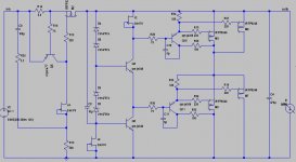
To scale to a higher voltage the idea is to stack more levels as you can see in the attached schematic. This also helps with higher shunt current; however, one can also parallel more mosfets for higher current. The problem I had with this was that the output impedance became huge starting already in the audio band. The solution seems to be driving the mosfets with one more pnp device as shown in the schematic. This brings a significant improvement in the output impedance, especially at higher frequencies. The C-E small cap has to be adjusted to safeguard against oscillation; higher value, safer, but it impacts the output impedance.
Please feel free to comment, point out problems.
Attachments
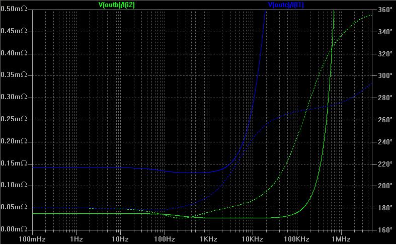
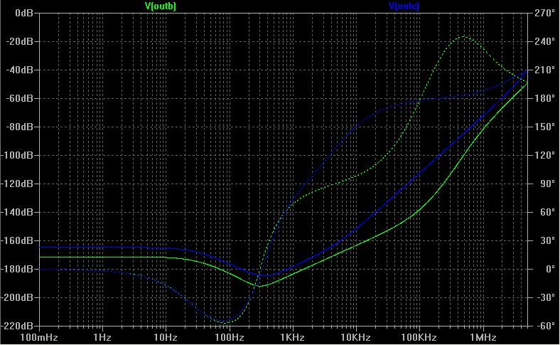
Here are the output impedance and line regulation plots, as compared to the original shunt (one version of it).
OK, so this is highly experimental, untested in reality.
OK, so this is highly experimental, untested in reality.
Stacking is the answer for very high voltage of course. From here to a practical VHT shunt, only practical tests can tell. How we call this idea? ''Totem Turbo Salas''?
Stacking a couple of turbo driven Ikoe'd Salas shunts can mean really high voltage experiments. I warn extreme caution. Seriously. SITT happens.
Hello Salas,
I'like to make a single 6c45 driver stage using this point of work :
Tube Gm Pa(max) Pg2(max) B+ Vp Vg2 Rk Ip Pa Ig2 Pg2 Rl 5% THD Vo 10V THD Gain
6C45p-e CCS 45 7.8 NA 400 194 NA 100 35.0 6.8 NA NA CCS 119 0.07 41
as indicated as best in:
http://www.pmillett.com/pentodes.htm
I'd like to use your "Anti-Triode SEPP, how to do best?"Post #66
schematic as css but I need 35mA for each tube , may be ok?
and this Shunt reg.
WHich is in you opinion the minimum current I must set on the shunt CSS for a stereo set up (two 6C45)? I've not a too big transformer .
Thanks a lot.
Ciao
Guglielmo
Salas, congratulations on a 15 page thread !
Is there a final (proven) schematic that you can post here please?
Is there a final (proven) schematic that you can post here please?
guglielmope said:Hello Salas,
I'like to make a single 6c45 driver stage using this point of work :
Tube Gm Pa(max) Pg2(max) B+ Vp Vg2 Rk Ip Pa Ig2 Pg2 Rl 5% THD Vo 10V THD Gain
6C45p-e CCS 45 7.8 NA 400 194 NA 100 35.0 6.8 NA NA CCS 119 0.07 41
as indicated as best in:
http://www.pmillett.com/pentodes.htm
I'd like to use your "Anti-Triode SEPP, how to do best?"Post #66
schematic as css but I need 35mA for each tube , may be ok?
and this Shunt reg.
WHich is in you opinion the minimum current I must set on the shunt CSS for a stereo set up (two 6C45)? I've not a too big transformer .
Thanks a lot.
Ciao
Guglielmo
For 2 channels running at 35mA each, 120mA in shunt wil suffice.
Hello Salas,
How can I add to your shunt regulator a start up delay for anode tube PSU?
HAve a nice day.
Ciao
Guglielmo
How can I add to your shunt regulator a start up delay for anode tube PSU?
HAve a nice day.
Ciao
Guglielmo
guglielmope said:Hello Salas,
How can I add to your shunt regulator a start up delay for anode tube PSU?
HAve a nice day.
Ciao
Guglielmo
Why not installing a different switch for the filaments so you can power them up ahead? Very simple.
Yes,
it may be very simple.
I was looking for something automatic but it can be a solution.
Another question:
If I need 495V as output I must change the IRF840?
Any suggestion?
Thanks a lot
Ciao
Guglielmo
it may be very simple.
I was looking for something automatic but it can be a solution.
Another question:
If I need 495V as output I must change the IRF840?
Any suggestion?
Thanks a lot
Ciao
Guglielmo
It can't work because I haven't used a pnp driver with more than 400V spec first of all. I could think of cascading and such but without a working prototype to ensure success you will end up with a blown experiment with theoretical suggestions most of the time. Sorry, you must find another solution. Maybe Janneman's recent Elektor one goes up to 500V and delivers much current?
Hi Salas
After reading this thread I built the regulator based on your design.
Very quiet, no huming at all But I get alot rusting noise, the type of noise coming from transistors when they become old.
Do you know what is the cause? Is it coming from the pot?
Thank you for helping
Audiohifi
After reading this thread I built the regulator based on your design.
Very quiet, no huming at all But I get alot rusting noise, the type of noise coming from transistors when they become old.
Do you know what is the cause? Is it coming from the pot?
Thank you for helping
Audiohifi
- Home
- Amplifiers
- Power Supplies
- Simplistic mosFET HV Shunt Regs