No 2 is working...
It is basically the same as my previous one with much better P-P layout (I think), the IRF840
substituted with IRFS450 (had some on hand) and R1=22R. So far no problems at all, only
observation is that Q1 is taking far more heat than the shunt Mosfet.
Vin is 250V, Vout=~200V.
I observed this behaviour in all of my variations so far, contrary to Salas' predictions...
Any thoughts on this?
Edit. That was connected to the amplifier playing music.
If your amp is getting the juice, the shunt (Q3) will be relaxed. The high dissipation noted for Q3 on the schematics is max, when on zero load, steady state. The harder you play the amp, the cooler Q3's sink will appear. When the CCS Mosfet (Q1), is always working at max. If setting the shunt say form 70mA to 100mA, there will be much more perceived heat due to steady dissipation from Q1 than maybe thought of, if keeping the same sink size. Q3 is working back and forth with the load, giving rest time to its sink. Q1 accumulates heat on its sink at all time. But the TO-240 CCS Mosfet is heavy and reliable, don't worry much if the sink is not really on the edge of  . Just back it down on CCS a little if the sink at hand proves a bit stressed. Also always check the total Vdrop of the Led string. If a bit stronger for Vdrop, then they can be setting the CCS 10-20% stronger than needed (depends on Vgs tolerance of each Q1 part too). 10-20% can make a lot of heat difference on a sink when there is constant current. By measuring the Vdrop on the CRC pre filter resistor and dividing by its nominal value, you will know the CCS current, no need for connecting a DVM in series.
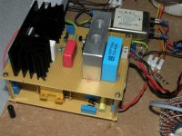
Nice that you got it working on first shot. Congrats. This is no7 made. I guess that a photo of it, a photo of its layout, and a few words about its construction and set up, can help future constructors. Are you going to use it double mono? Or is it for another circuit?
. Just back it down on CCS a little if the sink at hand proves a bit stressed. Also always check the total Vdrop of the Led string. If a bit stronger for Vdrop, then they can be setting the CCS 10-20% stronger than needed (depends on Vgs tolerance of each Q1 part too). 10-20% can make a lot of heat difference on a sink when there is constant current. By measuring the Vdrop on the CRC pre filter resistor and dividing by its nominal value, you will know the CCS current, no need for connecting a DVM in series.Nice that you got it working on first shot. Congrats. This is no7 made. I guess that a photo of it, a photo of its layout, and a few words about its construction and set up, can help future constructors. Are you going to use it double mono? Or is it for another circuit?
But the TO-240 CCS Mosfet is heavy and reliable, don't worry much if the sink is not really on the edge of *fire*
Heatsinks are large as in my first one... max. temperature so far is..well... I can still safely touch it without burning my fingertips.
I was using different Led's this time so my Led string is at 5.08V. Will try to determine my CCS current tonight, and also snap a few pictures.
I am not planning on double mono because my Aikido will be a battleship of headphone amplifier already. 😉 My first shunt reg was intended for another project (SE spud) and will be put to use once I get around to it.
Didn't have time to update your schematic but parts values are mostly as in the first schematic (post no 39?), with the exception of the IRFS450 (plus 1K stopper), an added 50R base stopper on the MPSA92 and C2 being 0.47uF. Most of this was due to parts availability in my drawers 😉 .
You mentioned that variations in the Led string can cause changes in the CCS current which seems to be the case on this one. Voltage drop across the pre filter resistor divided by the value of R equals only 70mA, so I might play with R1 again (Led string = 5.1V).
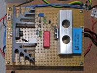
When you know what you are doing 🙂D ) construction is pretty straightforward; before I built the second one I had a long look at Gary P's layout and tried to combine that with my need for two individual heatsinks. I was also able to stack the shunt on top of my prefilter which makes a nice and compact unit and much tidier wiring.
You mentioned that variations in the Led string can cause changes in the CCS current which seems to be the case on this one. Voltage drop across the pre filter resistor divided by the value of R equals only 70mA, so I might play with R1 again (Led string = 5.1V).
When you know what you are doing 🙂D ) construction is pretty straightforward; before I built the second one I had a long look at Gary P's layout and tried to combine that with my need for two individual heatsinks. I was also able to stack the shunt on top of my prefilter which makes a nice and compact unit and much tidier wiring.
Attachments

I think the shunt current issue has been discussed already, but this is my 2 (euro) cts worth.
The shunt current is only the result of the design, not a goal.
You only have to calculate the CCS current. The series CCS needs to source at least the max load current. So, set it to, say, 120% of the max expected load current for some safety margin.
That's it. The shunt is designed to take up any slack between the CCS current and the load current and this will happen automagically. If for some reason the load current would drop all the way to zero, the shunt will take all of the CCS current. If the load current gets up to the expected maximum, the shunt will take the remaining 20% (in this example) of the CCS current.
Hope this helps.
Jan Didden
Hi Salas,
I have been reading through the whole thread, and I am deeply interested by your good design. That got me thinking seriously of replacing the poorly performed tube-based series regulator that I have been using in my existing pre-amp (a DIY creation) for the passed 5 years. This tube-based regulator was an adaptation from the one used in the Jadis JP200.
Before I go ahead with the change, I will very much appreciate if you could advise me on the questions below.
Following is my current situation:
Tranformer secondary = 300-0-300V, 120mA, 50Hz
Load current at idle = 14mA @ 300Vdc
Load current at max = 24mA @ 300Vdc
Tube regulator heater consumption = 6.048W (EL86 + EF86)
Pre-filter to the regulator is in CLC with capacitors = 2x47uF, 500V; and inductor = 10 Henry, 300 Ohm
I can see by converting to SS shunt regulator, I can re-allocate 6.048W of heater power to become part of the Iccs, so that I can keep power demand to the transformer roughly the same.
I believe the high voltage version of your design you posted earlier in this thread will be perfectly for me with minimal change. Iccs of 44mA will be more than 3 time of the idle current of my load. I will set output voltage to 300Vdc.
Questions:
1. I would like to keep the CLC pre-filter configuration and the lovely Jensen 47uF capacitors, what spec of inductor shall I change to?
2. I got whole bunch of BC556B, can I use them in place of of BC560B? Any base stopper need to be added?
3. Which capacitor C1, C2, or C3, has the most influence on the sonic performance of this circuit?
4. For Iccs of 44mA an Vout of 300V, approximately how much current will flow through R3 under max load of 24mA?
5. If I want to drop Iccs to 38mA, what will be the value for R1?
Many thanks to your for help.
Regards,
Johnny
jtcc1015 said:Questions:
1. I would like to keep the CLC pre-filter configuration and the lovely Jensen 47uF capacitors, what spec of inductor shall I change to?
2. I got whole bunch of BC556B, can I use them in place of of BC560B? Any base stopper need to be added?
3. Which capacitor C1, C2, or C3, has the most influence on the sonic performance of this circuit?
4. For Iccs of 44mA an Vout of 300V, approximately how much current will flow through R3 under max load of 24mA?
5. If I want to drop Iccs to 38mA, what will be the value for R1?
Many thanks to your for help.
Regards,
Johnny
1. Your inductor seems OK. It will drop only about 10V at say 35mA CCS. Since your transformer is 300-0-300, I think that you can use half of it (300-0) with 4 fast diodes as a bridge. Because you will use relatively low current, maintain 100V Vin-Vout if your transformer and mains allow, it helps transient performance with low CCS. That means 3.5W constant dissipation for Q1 if CCS is 35mA for example. Not too demanding on a sink. If it will shoot over 400V DC in (unlike), you can always use an R before first C, and adjust.
2. Yes, you can use them. Use 27R base stopper for 2N6520 as a precaution for stray inductance in the construction. If you can find MPSA94 easier, it looks like working too.
3. C2, C1.
4. 3.65mA, 1.1W dissipation.
5. 56R is the ballpark given the average Vgs and LEDs I used, but start with 68R and measure, because in practice, LED drop, Vgs, Vin, Q2 type, vary and influence.
janneman said:The shunt current is only the result of the design, not a goal.
You only have to calculate the CCS current.
Good to know for sink allowances non the less.
janneman said:Hope this helps.
Jan Didden
All kindness helps. Thanks Jan!
Hi Salas,
Thanks for your prompt reply. Will get it done as soon as I get all the parts.
Regards,
Johnny
Thanks for your prompt reply. Will get it done as soon as I get all the parts.
Regards,
Johnny
Salas,
I built one of your shunt regs and can not get it above 75 volts. I am using a 230v ac tranny and the low power version at the beginning of this post. Before I triple check everything again, is there something in particular I should be looking at. One thing is that the LED's might have been 1.8 v vs 1.7.
Thanks
John
Something is not providing enough current to the 82k resistor so to rise more than 75V. Check the orientation and health of all small transistors first. Do you use the exact parts? If orientation and health is OK, see that all else is properly done, and then you may try using a smaller R5.
Guys, I've been away from "parts bbq" for a while, has anybody successfully finished a HV and high current version? Something for a 110mA load would be what I'm aiming for. I'm still waiting for a bunch of 9240s and 840s to arrive from HK and then I'll be back in the game with a vengeance 😀
In the meanwhile I acquired a nice HUGE tektronix 502a tube dual beam oscilloscope, with a 100uV/div sensitivity. It's a nice toy. Checked the low voltage salas shunt that I'm using with the phono stage and it shows output ripple in the 200uV range.
In the meanwhile I acquired a nice HUGE tektronix 502a tube dual beam oscilloscope, with a 100uV/div sensitivity. It's a nice toy. Checked the low voltage salas shunt that I'm using with the phono stage and it shows output ripple in the 200uV range.
Transformer Specifications
Hi guys,
I'm about to order the transformer to power the shunt regulators for my preamp - FVP5a. The current required for each channel is about 30mA thus I'll be running the regulators at 60mA according to Salas recommendation (twice the current required by the audio circuit).
I'm going to use one regulator per channel with just one transformer with dual secondaries - I don't have room in my enclosure to fit two transformers.
The circuit requires 250V DC.
Is a transformer with 2x 240V AC / 200mA OK for this?
After rectification I'll get ~238V DC which after the CRC filter @ 60mA will give me about 325V DC (220R between the two capacitors).
This will give me more than 50V drop across the IRFP9240 and current wise I think the transformer will handle the required current with a good margin of power to spare.
Take care,
Luis
I am usually spec'cing my transformers for at least twice the required current. For me a mains transformer can't be big enough...😉
In your case 200mA might be just fine, but when you have it custom wound anyway I would go a little higher.
PS. How did you arrive at approx. 325V ? PSUD doesn't give me more than 310V max with your numbers...
In your case 200mA might be just fine, but when you have it custom wound anyway I would go a little higher.
PS. How did you arrive at approx. 325V ? PSUD doesn't give me more than 310V max with your numbers...
I fully agree. A bigger transformer is always of benefit, even in a preamp. I am willing to bet that even a "golden ear" would be really hard pressed to tell the difference between a dual mono power supply with 2 x 25va transformers and a power supply with two bridges and a single 50va transformer.
ikoflexer said:Guys, I've been away from "parts bbq" for a while, has anybody successfully finished a HV and high current version? Something for a 110mA load would be what I'm aiming for. I'm still waiting for a bunch of 9240s and 840s to arrive from HK and then I'll be back in the game with a vengeance 😀
In the meanwhile I acquired a nice HUGE tektronix 502a tube dual beam oscilloscope, with a 100uV/div sensitivity. It's a nice toy. Checked the low voltage salas shunt that I'm using with the phono stage and it shows output ripple in the 200uV range.
My 502A stopped working, but it did come with the original manual. Let me know if you need some pages scanned.
Jim
- Home
- Amplifiers
- Power Supplies
- Simplistic mosFET HV Shunt Regs