At least double saturation current spec for the choke than the CCS setting.
Double current from the CCS, or from the total current consumption?
Choke saturation margin to be CCS setting X 2. The consumption after the choke can't top the CCS setting. Constant draw is ideal for choke pre filtering BTW. Especially choke input.
At least double saturation current spec for the choke than the CCS setting.
So for 36mA = 75mA? If can't get 75mA wich will be better 65mA or 100mA?
With such current (36mA) can supply B+ for two 6922 tubes or I need 30mA per tube so 60mA because I have only one HV reg?
If only have one HV reg how much current to supply B+ for one ECC83 & one 6922?
Last edited:
If only have one HV reg how much current to supply B+ for one ECC83 & one 6922?
You probably know best... how much current do one ECC83 and one 6922 draw in your circuit? Maybe not that much in a preamp, so let's say 3 + 5mA = 8mA...
Now make that double (approximately 😉)
I still have set the shunt reg (one for two channels) in my C3G headphone amp at around 80mA... simply because I was too lazy to change R1 which was chosen for another amplifier. My tubes consume about 15mA each so that makes 30mA. I have good heatsinks so I don't mind the excess 50mA... and it sounds glorious.
When this one will be cased up I will build (yet) another SSHV and set it at about 65mA (and make it as compact as possible).
You probably know best... how much current do one ECC83 and one 6922 draw in your circuit? Maybe not that much in a preamp, so let's say 3 + 5mA = 8mA...
Now make that double (approximately 😉)
I assume that you are speaking about setting the reg current not choke, right?
Yes, since you were asking about current setting.
But I also misread your first question 😉... I would go for the bigger choke.
(Btw, I just added one to the pre filter in my Aikido... (with Salas shunt)
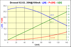
Maybe you are finding this interseting also... chokes are not static devices it seems.
http://www.roehrentechnik.de/html/reihe_m65.html -->see data
Reinhoefer has very good reputation around here, this is were I got my chokes and opt's...
But I also misread your first question 😉... I would go for the bigger choke.
(Btw, I just added one to the pre filter in my Aikido... (with Salas shunt)
Maybe you are finding this interseting also... chokes are not static devices it seems.
http://www.roehrentechnik.de/html/reihe_m65.html -->see data
Reinhoefer has very good reputation around here, this is were I got my chokes and opt's...
finished adjustment for the dual 300-0-300V last night for Exstata, and it works nice on dummyloads.
The SS modules have a very high Resistance, for like 1 sec, until its "fully" powerd up. Is it likely, that it will blow anything in the shunt PS (that always needs a load)?
The SS modules have a very high Resistance, for like 1 sec, until its "fully" powerd up. Is it likely, that it will blow anything in the shunt PS (that always needs a load)?
finished adjustment for the dual 300-0-300V last night for Exstata, and it works nice on dummyloads.
The SS modules have a very high Resistance, for like 1 sec, until its "fully" powerd up. Is it likely, that it will blow anything in the shunt PS (that always needs a load)?
If the load does not consume current for a while, then almost the total available from the CCS part it is consumed in the output Mosfet of the reg itself. As long as its sink can support that for a minute, nothing bad will happen to the reg. If its really only a for a sec, no worries.
P.S. Let us know how it went.
HI Salas, what's the voltage in limit for your HV shunt? With 340V in I just killed mosfet 🙁
R1 is 21ohm load 300V load near to 70mA
R1 is 21ohm load 300V load near to 70mA
Which Mosfet? Both?
The limit is the output loop's parts max (the BJT's and the shunt Mosfet's). The input must not rise beyond 200V VDS max as a difference not to kill the input CCS Mosfet also. Something specific must have happened. Give us more details about the set up. Maybe you got some Zener and its a PCB?
The limit is the output loop's parts max (the BJT's and the shunt Mosfet's). The input must not rise beyond 200V VDS max as a difference not to kill the input CCS Mosfet also. Something specific must have happened. Give us more details about the set up. Maybe you got some Zener and its a PCB?
Are there Zeners installed? Especially a single bigger one? If yes,take it out. Is there enough consumption, load connected? Is the load something new that you haven't had before?
at start up the output is at 0Volts.
The input will rise very quickly to your PSU voltage.
The CCS FET acts as a CCS to charge up the zero volt side to 300V.
340Vdc * 0.07A = 23.8W at the start of charging. Tj is going to rise very quickly.
The temperature de-rated maximum dissipation might be exceeded for the first few hundred ms.
But the Voltage rating has also been exceeded until the output has risen to 140Vdc. By then the FET has blown, due to excessive Vds combined with excessive Tj.
You should really use a 400V device for a 340Vdc supply that could vary +-10%, i.e. 310 to 370Vdc.
The worst case dissipation for the CCS FET is to short circuit the output.
In this situation I would expect the CCS FET to survive even though it might be operating with Tj = 149degC
That's how I determine the heatsinking requirement for this survive during fault mode.
It's the quangaho version of your shunt. I just change R1=20ohm to get 100mA and both mosfet+2sk170 gone for two times! 🙁 V-in was around 340volts to get 300V-out
Hi!
If V-in more 320Vto 380V, so you change R =56K/5W by 82K/5W,
And If you like v-out more 280V to 320V,
you have to change R4=120k by 150K-180K, K170 is safe!
Yes salas, zeners are mounted, include the big one over the IRFP9610. No the load is not new, but I changed the voltage from 250 (with no problem) to 300V
Quan I'll modify the R you suggested
Thank you all!!!
Quan I'll modify the R you suggested
Thank you all!!!
- Home
- Amplifiers
- Power Supplies
- Simplistic mosFET HV Shunt Regs