Yes, I also think that I have to use a bigger heatsink.
Salas do you believe that the shunt masks the sound of lesser quality parts in the psu (mainly capacitors)?
Salas do you believe that the shunt masks the sound of lesser quality parts in the psu (mainly capacitors)?
Yes, it covers differences between rectifiers or capacitors a lot compared to passive filters. Its not a belief, I checked it out.
UF diodes and Nippon Chemicon can take you 80% near tube rectifier and select caps. Basically, the idea behind it, is great sound on the cheap, no worries. I hated all those chokes and Cerafines that broke the bank just to get a buzz in the end in phono stages.😀
They are supposed to run hot. We are using healthy current margins in constant. I always suggest about double the audio circuit's idle needs because I like them to swing freely and clip and still have fuel in the tank. That sounds it so too. But if some build has to use a so so sink etc. you can always judge in practice by listening what is the lowest threshold that the sound is good enough and leave it there so to avoid excess heat. For instance, You wanted 100mA for 50mA idling audio circuits. You hit 113mA with given Leds and IRFP VGS. Maybe your sound can be dynamic still at 80mA. Gets to test.
Marinos, it may surprise you how much it can relax if you go under about 100mA compared to 113mA.
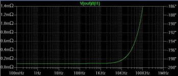
ikoflexer said:I may as well add something about the new shunt. First, Marino, congrats! My shunt runs hot too. The amp+shunt draws something like 220mA all in all. The shunt mosfet works happily at about 24W (measured), and it enjoys a good size heat sink, but I think I should use a larger one, because this one gets hot to touch. The CCS mosfet is barely warm. The scope shows an output trace which is basically a flat line at 226V DC.
Iko, what circuit did you end up with? Had a listen?
Salas said:
Iko, what circuit did you end up with? Had a listen?
Sorry salas I didn't get back to you with details. I attached the circuit that is currently plugged in and works. A number of variations also worked, started safe without jfets, also with bc560 bias, etc., and when it worked I got bolder and arrived at this configuration. I have rebuilt the power supply for this one; perhaps something in my older psu reacted very badly with previous shunt attempts. I'm still thinking that the regulator sinks probably to little current. I know for sure that the tube circuit draws about 109mA, which leaves another 100mA or so for the shunt, since the total draw is about 210mA. I know you recommend to have the shunt draw about double.
I have listened to it a little bit, but I cannot tell the difference yet. I have a bit of buzz in the circuit, buzz which comes from the tube amp, so I have to take care of that before I can say more about the sound. I think I'm still a bit far from the finish line. I do want to take this opportunity to thank you again for your support. It can get really tough when things keep on going wrong, and parts keep on getting zapped.

Edit: forgot to attach the schematic.
Attachments
You are welcome. Told you, you will not remain without a shunt. It takes faith.🙂
So that is the V2 from email (with LEDs) plus the JFETs CCSs from V1. This mix is a really low ripple, fixed voltage shunt. Is C1, 1 or .1uF? 1uF gives a bit of a slow start, nice if stable. Also is R13 a virtual resistor? Did not need a tad degeneration in the end? I guess there must have been something really strong in that 680uF 2H 1360uF computer cap pre filter, maybe too much inrush plus inductance in caps, it was always bugging me. Now you use low uf CLC and RC? You will never need too much pre filtering since the gm*load impedance of the driver BJT gain loop is very strong now due to local Jfet CCs. Can you show, its simulated ripple rejection, output impedance and step?
So that is the V2 from email (with LEDs) plus the JFETs CCSs from V1. This mix is a really low ripple, fixed voltage shunt. Is C1, 1 or .1uF? 1uF gives a bit of a slow start, nice if stable. Also is R13 a virtual resistor? Did not need a tad degeneration in the end? I guess there must have been something really strong in that 680uF 2H 1360uF computer cap pre filter, maybe too much inrush plus inductance in caps, it was always bugging me. Now you use low uf CLC and RC? You will never need too much pre filtering since the gm*load impedance of the driver BJT gain loop is very strong now due to local Jfet CCs. Can you show, its simulated ripple rejection, output impedance and step?
Yes, this one simulates a flat line for output; no ripple out, with a 5V ripple in. C1 is a 0.1uF polypropylene cap. I decided to stay safe with a small value. In the real circuit R13 is 0.2R resistor. The regulator seemed stable without it too, but I wanted to try it and then just left it there. Let's just say this is not the final version.
The filtering now is just as shown in the schematic, CLCRC, perhaps too much. I'll post some sim results soon.
The filtering now is just as shown in the schematic, CLCRC, perhaps too much. I'll post some sim results soon.

Do you think that this notch can be there for real? How can it be compensated in sim? Some pF cap on some semiconductor? Or is it the pre filter? The rejection in dB range is fantastic. It will be just great if it manages 40% worse in reality with layout, cabling etc.
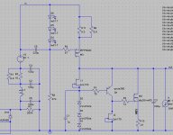
Output impedance attached here.
Edit: forgot to attache the result of the transfer simulation (in spice, .tf v(out) v1):
--- Transfer Function ---
Transfer_function: 3.26799e-008 transfer
v1#Input_impedance: 2647.66 impedance
output_impedance_at_V(out): 9.4063e-005 impedance
Edit: forgot to attache the result of the transfer simulation (in spice, .tf v(out) v1):
--- Transfer Function ---
Transfer_function: 3.26799e-008 transfer
v1#Input_impedance: 2647.66 impedance
output_impedance_at_V(out): 9.4063e-005 impedance
Attachments
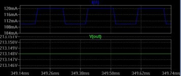
This may seem too fantastic, but we have seen it measured doing the same trick in the low voltage cousin, so I tend to buy it.🙂
Salas said:Do you think that this notch can be there for real? How can it be compensated in sim? Some pF cap on some semiconductor? Or is it the pre filter? The rejection in dB range is fantastic. It will be just great if it manages 40% worse in reality with layout, cabling etc.
Unfortunately I don't have the equipment to measure line regulation in reality and plot it like that. Not using the bootstrap cap gets rid of the notch, see attached image. I have also been experimenting with small value caps (33-100pF) between the base of the driver pnp to ground. But that worked only for the non-led version.
Edit: oops, attached wrong image; fixed now.
Attachments
I prefer it without the bootstrap. Or with another value of bootstrap. I think I did not have a bootstrap in the Leds V2 I emailed. Ripple rejection is great anyway, there is pre filtering, I know that smooth phase sounds more open. I trade numbers for smooth trends any day. 
Great work Iko! Not only you have done it in the end, but you have the most powerful, most technically advanced HV shunt of the Simplistic family working on your bench! 
You're too funny!  We should really be more serious and make it even stronger. To supply 1A at 500V would not be too bad 😀
We should really be more serious and make it even stronger. To supply 1A at 500V would not be too bad 😀I think it can make it as it is. Its stable, it will. Monster heatsinks, minute R1, and lets power an Audio Research 2X200W main amp. Its just a matter of scale. Imagine how a valve muscle power amp will transform its sound if fed regulated as a whole from a monster Mosfet shunt! Heat abundance, tolerated in Canadian climate only. Wow! Not Ecological, but Ikological!
You must be kidding! Pics of the prototype? It's a mess right now, I've been soldering and desoldering parts like never before, on the same platform. when I finish experimentation I'll build a fresh one, put it together with the amp, and then take some pics of the final version.
- Home
- Amplifiers
- Power Supplies
- Simplistic mosFET HV Shunt Regs