the high open loop gain (750x in my simulation) does need to be address. a few thoughts:
1) lower the collector resistor on the input stage;
2) lower the collector and bootstrap resistors on the phase splitter stage. Be careful however as you may accidentally increase the bias on theoutput stage;
3) use degenerative resistors throughout the amp.
4) use mosfets or jfets as they have lower gains.
5) get rid of the bootstrap on the phase splitter.
6) use a power resistor in serial with the load.
adding attenuation isn't bad idea as long as it isn't too much.
I think it can be made to work. Just how one wants it to be done.
Not quite matching the requirements...
...as it has whopping 5 BJTs and NFB:
http://www.linearaudio.de/scratch/new-se-1b-lp.pdf
Gives 3W @ 6Ohm from +-6.5 Supply,
Iq=1.1A, simulated THD 0.025% @1.5W
So, NFB is good for you, isn't it?
Best Regards,
Peter Jacobi
...as it has whopping 5 BJTs and NFB:
http://www.linearaudio.de/scratch/new-se-1b-lp.pdf
Gives 3W @ 6Ohm from +-6.5 Supply,
Iq=1.1A, simulated THD 0.025% @1.5W
So, NFB is good for you, isn't it?
Best Regards,
Peter Jacobi
continue thread?
hmm... i like this thread.
any more ideas on simple BJT amp?
How about a cascode BJT front-end driving darlington emitter followers?
take some feedback back to the BJT frontend.
looking around 5-10W of power. Run from 12v SLA batteries.
something similar to the AR-3 headphone amp..
hmm... i like this thread.
any more ideas on simple BJT amp?
How about a cascode BJT front-end driving darlington emitter followers?
take some feedback back to the BJT frontend.
looking around 5-10W of power. Run from 12v SLA batteries.
something similar to the AR-3 headphone amp..
I have designed and built this amp as a learning step for some friends that have shown interest in building there own amps.
Its design is simple and cheap and works quite well. If class A use is needed then a high bias current and larger heat sink could be used to cover the output goal by changing the current of the vas. If not the amp puts out roughly 5 watts peak in AB mode.
There are only 2 different resistor values used.
Attachments
How about this?
A simple BJT gain stage... say a MPSA18 with a 1.2K load from a +24v supply. This DC coupled to a darlington 2N3055 running at 3A or about there.
Can I use the output stage load.. i.e. the 3A through a 4 ohm emitter load to tap the current for the input stage? kind of a feedback?
so instead of the input stage emitter to ground... run it through the output emitter resistor...
dunno if this would work...
maybe this is a type of feedforward?
perhaps If I use JFETS in the input stage it would work.. hmmm...
I've never formally drawn it out, but I had an idea for a very simple 2 stage all FET amplifier several years ago consisting of quasi 'common source' complementary JFET inputs with their gates both driven by the input signal directly driving common source complementary MOSFET outputs with the signal & bias stabilization feedback being taken back to the JFET sources. The lowish breakdown voltages of available jfets probably can be enhanced with a capacitor bypassed zener & small resistor to realize an amplifier up to the 1-200 watt range with only 'four' topologically required active devices (although more input stage transconductance may be gotten, if needed by paralleling input JFETs, & output devices parallelable as needed also for higher currents🙂). Output stage biasing may be achievable with local DC loops with common AC feedback. DC signal coupling may also be feasible with this approach.
Fuling...
Thats an interesting schematic...
How do I make the input stage more linear??? Do I just increase the supply voltage and increase the load resistor on the input stage?
How do I take feedback from the output back to the input transistor on this circuit?
Is it easier to use a JFET input?
What kind of power and distortion levels did you get out of that circuit?
and more importantly, how did it sound?
Would it be "better" to cascode the input stage?
Thanks!!!
AudioGeek:
Whoa, that´s alot of questions!!
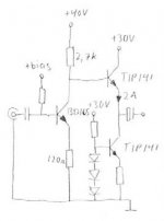
I guess higher supply voltage and load resistance might work, yes. The input stage employs local current feedback (no decoupling cap at the emitter resistor) so I guess it´s quite linear already.
BTW: If you change the ratio between the two specified resistors (2,7k and 120R) you also change the gain.
If you want global voltage feeback I guess you can put a resistor between the output and the emitter of the BD165. Something in the 1-2k range maybe. Haven´t tried it since I like the absence of (global) negative feedback.
No idea about JFET´s or cascoding. I remember that I used an BJT input buffer sometime to increase the input impedance.
Just a BC546C and some resistors.
How did it sound?? Well, to quote one of my classmates:
"Wow, now I can hear what the bassguitar plays!"
I got about 10W @ 8 ohms.
Whoa, that´s alot of questions!!
I guess higher supply voltage and load resistance might work, yes. The input stage employs local current feedback (no decoupling cap at the emitter resistor) so I guess it´s quite linear already.
BTW: If you change the ratio between the two specified resistors (2,7k and 120R) you also change the gain.
If you want global voltage feeback I guess you can put a resistor between the output and the emitter of the BD165. Something in the 1-2k range maybe. Haven´t tried it since I like the absence of (global) negative feedback.
No idea about JFET´s or cascoding. I remember that I used an BJT input buffer sometime to increase the input impedance.
Just a BC546C and some resistors.
How did it sound?? Well, to quote one of my classmates:
"Wow, now I can hear what the bassguitar plays!"
I got about 10W @ 8 ohms.
no local but global?
how do I change the circuit for NO local feedback of the input BJT but global feedback from output for gain of 10?
doesn't the TIP42 have too much base current for the input transistor??? Or is it a darlington?
Thanks!!!
how do I change the circuit for NO local feedback of the input BJT but global feedback from output for gain of 10?
doesn't the TIP42 have too much base current for the input transistor??? Or is it a darlington?
Thanks!!!
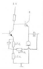
Maybe something like this:
This is the way feedback usually is done in tube amps and that´s what I do most. Can´t see why you want global feedback though.
There´s no TIP42´s in this circuit, the input transistor is BD165 and outputs are TIP142. Sorry if I did a typo earlier.
This is the way feedback usually is done in tube amps and that´s what I do most. Can´t see why you want global feedback though.
There´s no TIP42´s in this circuit, the input transistor is BD165 and outputs are TIP142. Sorry if I did a typo earlier.
Attachments
good point
I guess there is no real difference between the local and global feedback in this case since the output stage has very little distortionof its own.
Other than the local feedback on the emitter of the input, what else can be done to reduce distortion but keep the voltage gain on the input?
Also, what is the input impedance of the amp?
Thanks!
yeah i know... many questions.
If you want an amp that measures good you should probably looks elsewhere. I guess some Zen-looking input stage would work, ie a CCS loaded mosfet with feedback from drain to gate.
But that would be a completely different amp.
I think I measured the input impedance once but I can´t for my life remember the results.
An input buffer might be a good idea if you´re going to feed it from a CD player, but any SS preamp should be able to drive it without buffer.
If you´re going to try this amp my advice is to keep the feedback topology as it is, since it works great.
As the pendulum now swings a bit in the more complicated direction, I'll volunteer this circuit:
http://www.linearaudio.de/scratch/IGBT-3.pdf
Just take Power Darlingtons instead of IGBTs to stay on topic.
The downside of this one (besides having a whopping 7 transistors in use), is that it is fairly standard in all aspects (except perhaps not having the "mandatory" LTP input).
Regards,
Peter Jacobi
BTW: If anyone has comments on using IGBTs in linear mode, you are invited to use either of these threads:
http://www.diyaudio.com/forums/showthread.php?s=&threadid=22408&highlight=
http://www.diyaudio.com/forums/showthread.php?s=&threadid=27307&highlight=
how about a combination of a JLH and a Aleph?
I was thinking about it on my flight back home and did some preliminary simulation and it seemed to work well.
It is essentially a JLH input stage + Aleph output stage. In theory, it needs just two transistors (plus a current source). But in reality, it is probably a three-transistor set-up.
I will post some results later but I have named it JLeph, 🙂
JLeph
here it goes. It is just a conceptual framework, tho.
some performance figures from simulation:
THD: 0.072% @ 1khz, 0.702% @ 10khz, 1.543% @ 20khz.
frequency response: flat upto 0.5mhz.
open loop gain: 30x.
not bad for a two-transistor design, 🙂.
it can also be easily converted to a dual-rail setup.
the key, i think, is to figure out a way to replace the constant current source. I am sure a choke will do but probably it is easier and cheaper to use a transistor CCS.
I experimented a little on the flight and it appears that normal CCS (LED+one transistor) doesn't work well for its excessive current drop. The best solution I have found so far is a N-channel mosfet with its gate bootstraped. I will post the schematic later.
Attachments
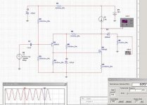
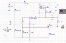
here is the JLeph with a N-channel CCS.
it idles at about 2.5a, adjusted by R12: larger R12 will cause larger idle current.
THD: 0.072% @ 1khz, 0.727% @ 10khz, 1.589% @ 20khz
the bootstraping is done by C5, R9 and R12.
I haven't built one yet. so don't know how good / bad it will sound.
it does have the advantage of low feedback (0.3x of feedback for the schematic presented here).
it doesn't have a whole lot of power: about 20vpp output, or 5w.
you can potentially use a choke to replace the N-channel CCS but you need to rebias the input transistor.
Attachments
increasing rail voltage to 72v, you can get to about 45vpp (idling at 4amp), and good THD performance (0.799% @ 20khz).
- Status
- Not open for further replies.
- Home
- Amplifiers
- Solid State
- simplest amplifier possible with BJT's?